Кому нужны навороченные готовые дроны, когда можно создать свой собственный шедевр? Этот гайд — ваш универсальный помощник в создании крутого дрона на базе Arduino. И поверьте, он будет круче (и, скорее всего, дешевле), чем любой дрон из магазина.
Мы будем использовать плату Arduino в качестве мозга нашего квадрокоптера, программируя её для управления моторами, чтобы ваш дрон взлетел в небо. Представьте, что это большой летающий и настраиваемый робот, который вы сделали сами — как это круто!?
Этот гайд идеально подходит для тех, кто хочет:
- Испытать острые ощущения от создания дрона с нуля
- Узнать основы программирования Arduino и управления полётом
- Выпустить своего внутреннего безумного учёного (ну или просто любителя дронов)
Так что, если вы готовы отказаться от магазинных решений и создать что-то по-настоящему уникальное, надевайте свои воображаемые очки и приступим!
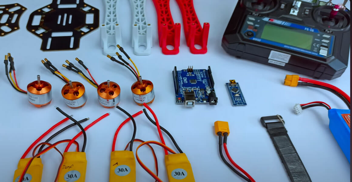
Необходимые материалы
Для создания этого проекта вам понадобятся:
- Каркас дрона F450
- Бесколлекторные моторы 1000 KV x4
- Регуляторы скорости (ESC) 30A x4
- Пропеллеры x4
- Модуль MPU 6050
- Литий-полимерный аккумулятор 2200 мАч
- Разъёмы XT60 (папа, мама, можно найти в любом магазине электроники)
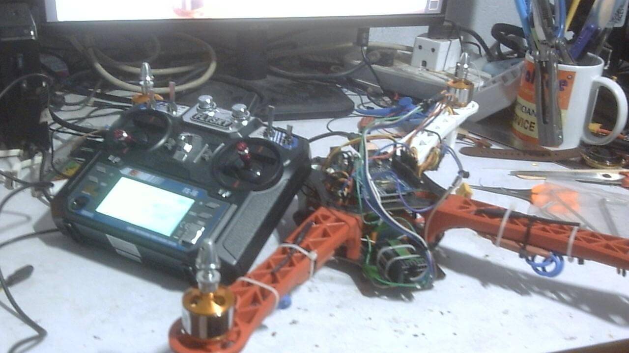
- Передатчик и приёмник Flysky FS-I6
Шаг 1: Пайка разъёма аккумулятора и ESC
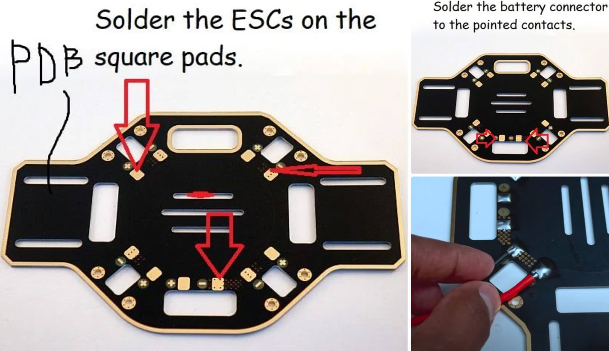
PDB (Power Distribution Board) — это нижняя пластина каркаса с квадратными площадками вокруг. Припаяйте ESC к PDB, как показано на изображении. Проверьте полярность!
Также есть дополнительные площадки для соединения аккумулятора. Припаяйте женский разъём XT60 к этим площадкам, убедившись, что красный провод идет к положительному контакту, а чёрный — к отрицательному.
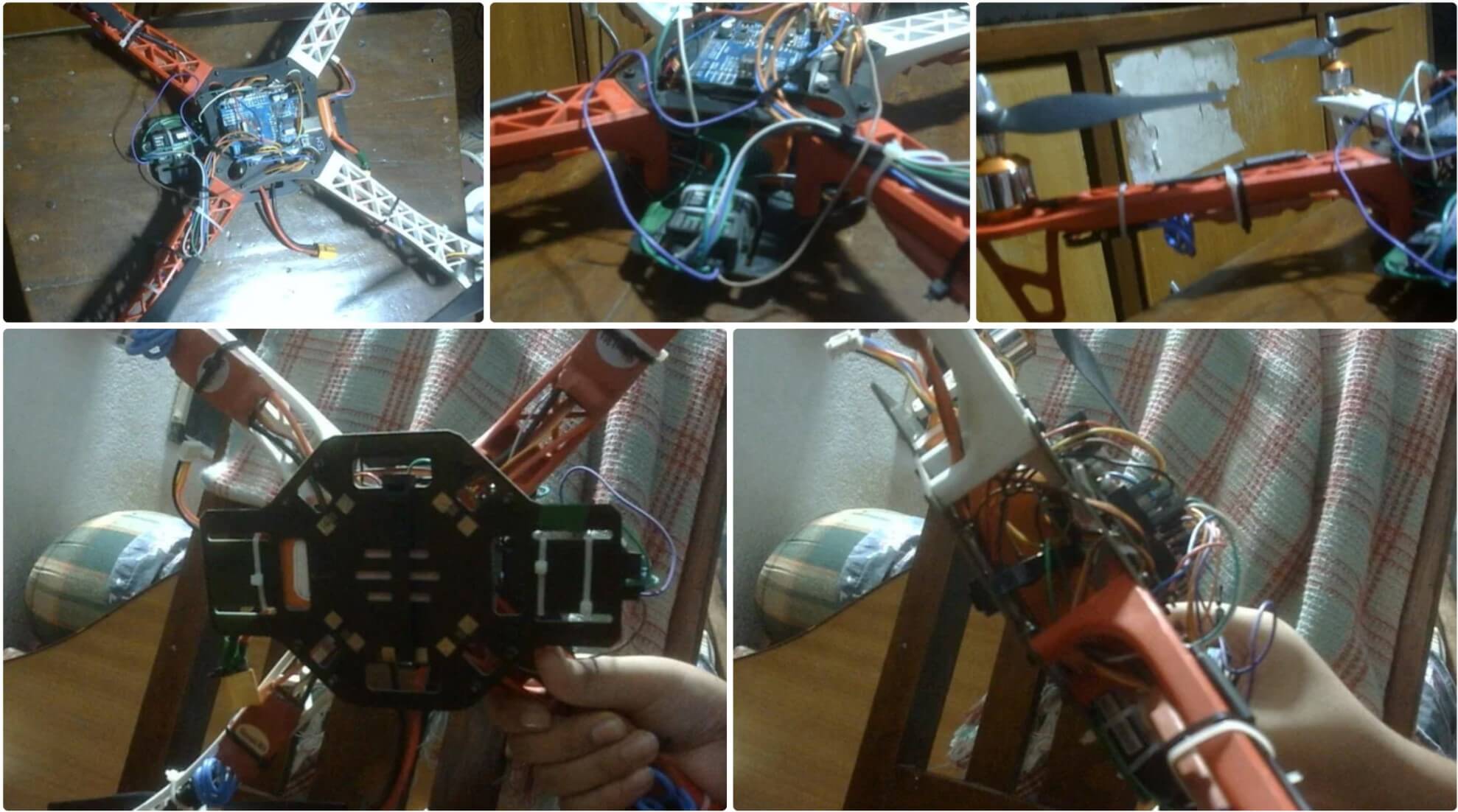
Шаг 2: Сборка каркаса
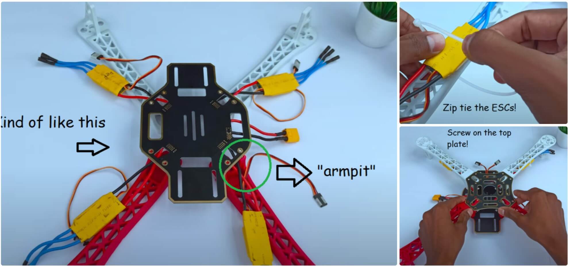
Теперь пришло время собрать каркас. Прикрутите «руки» к нижней пластине и проведите ESC через «подмышки» (маленькие арки). Затем закрепите ESC на нижней стороне каркаса с помощью стяжек. После обрезки лишнего пластика стяжек прикрутите верхнюю пластину. Это довольно просто, хотя там 16 винтов! Потеря хотя бы одного сделает верхнюю пластину очень нестабильной, а это плохо, так как на неё будем монтировать электронику. Так что, если потеряли винт, сразу найдите замену!
Шаг 3: Построение схемы
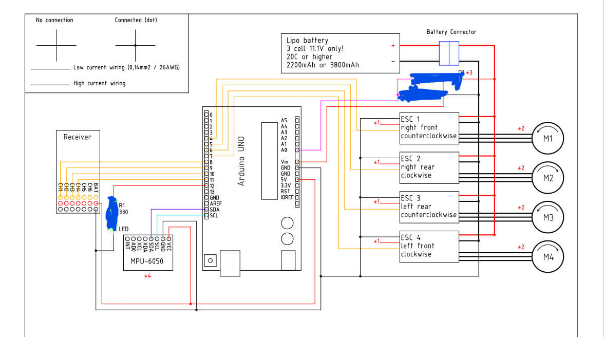
Вот схема подключения. Не беспокойтесь о затемнённых областях, это не важно. Этот дизайн был утомительным, и я даже случайно уничтожил старый Arduino Uno, работая над схемой питания.
Подключите все компоненты и постарайтесь аккуратно уложить провода, используя множество стяжек и изоленты. Я работаю над верхним корпусом и добавлю STL-файлы в следующем обновлении.
Использовал массивные стяжки, чтобы надежно прикрепить аккумулятор к нижней палубе каркаса дрона.
Шаг 4: Программирование дрона. Часть 1
Чтобы начать откройте Arduino IDE.
Совет: всегда запускайте Arduino IDE с правами администратора. Это решит множество проблем с загрузкой и доступом к Arduino через Serial Monitor.
Сначала откройте скетч ClearEEPROM и загрузите его. Если в Arduino загружены предыдущие скетчи, загрузите пустой скетч, а затем ClearEEPROM.
ClearEEPROM
#include

void setup(){
  for (int i = 0 ; i < EEPROM.length() ; i++){
    EEPROM.write(i, 0);
  }

}

void loop(){
  //Do nothing here...
}
DroneSetup
#include //Include the Wire.h library so we can communicate with the gyro
#include //Include the EEPROM.h library so we can store information onto the EEPROM
//Declaring Global Variables
byte last_channel_1, last_channel_2, last_channel_3, last_channel_4;
byte lowByte, highByte, type, gyro_address, error, clockspeed_ok;
byte channel_1_assign, channel_2_assign, channel_3_assign, channel_4_assign;
byte roll_axis, pitch_axis, yaw_axis;
byte receiver_check_byte, gyro_check_byte;
volatile int receiver_input_channel_1, receiver_input_channel_2, receiver_input_channel_3, receiver_input_channel_4;
int center_channel_1, center_channel_2, center_channel_3, center_channel_4;
int high_channel_1, high_channel_2, high_channel_3, high_channel_4;
int low_channel_1, low_channel_2, low_channel_3, low_channel_4;
int address, cal_int;
unsigned long timer, timer_1, timer_2, timer_3, timer_4, current_time;
float gyro_pitch, gyro_roll, gyro_yaw;
float gyro_roll_cal, gyro_pitch_cal, gyro_yaw_cal;
//Setup routine
void setup(){
pinMode(12, OUTPUT);
//Arduino (Atmega) pins default to inputs, so they don't need to be explicitly declared as inputs
PCICR |= (1 << PCIE0); // set PCIE0 to enable PCMSK0 scan
PCMSK0 |= (1 << PCINT0); // set PCINT0 (digital input 8) to trigger an interrupt on state change
PCMSK0 |= (1 << PCINT1); // set PCINT1 (digital input 9)to trigger an interrupt on state change
PCMSK0 |= (1 << PCINT2); // set PCINT2 (digital input 10)to trigger an interrupt on state change
PCMSK0 |= (1 << PCINT3); // set PCINT3 (digital input 11)to trigger an interrupt on state change Wire.begin(); //Start the I2C as master Serial.begin(57600); //Start the serial connetion @ 57600bps delay(250); //Give the gyro time to start } //Main program void loop(){ //Show the YMFC-3D V2 intro intro(); Serial.println(F("")); Serial.println(F("===================================================")); Serial.println(F("System check")); Serial.println(F("===================================================")); delay(1000); Serial.println(F("Checking I2C clock speed.")); delay(1000); TWBR = 12; //Set the I2C clock speed to 400kHz. #if F_CPU == 16000000L //If the clock speed is 16MHz include the next code line when compiling clockspeed_ok = 1; //Set clockspeed_ok to 1 #endif //End of if statement if(TWBR == 12 && clockspeed_ok){ Serial.println(F("I2C clock speed is correctly set to 400kHz.")); } else{ Serial.println(F("I2C clock speed is not set to 400kHz. (ERROR 8)")); error = 1; } if(error == 0){ Serial.println(F("")); Serial.println(F("===================================================")); Serial.println(F("Transmitter setup")); Serial.println(F("===================================================")); delay(1000); Serial.print(F("Checking for valid receiver signals.")); //Wait 10 seconds until all receiver inputs are valid wait_for_receiver(); Serial.println(F("")); } //Quit the program in case of an error if(error == 0){ delay(2000); Serial.println(F("Place all sticks and subtrims in the center position within 10 seconds.")); for(int i = 9;i > 0;i--){
delay(1000);
Serial.print(i);
Serial.print(" ");
}
Serial.println(" ");
//Store the central stick positions
center_channel_1 = receiver_input_channel_1;
center_channel_2 = receiver_input_channel_2;
center_channel_3 = receiver_input_channel_3;
center_channel_4 = receiver_input_channel_4;
Serial.println(F(""));
Serial.println(F("Center positions stored."));
Serial.print(F("Digital input 08 = "));
Serial.println(receiver_input_channel_1);
Serial.print(F("Digital input 09 = "));
Serial.println(receiver_input_channel_2);
Serial.print(F("Digital input 10 = "));
Serial.println(receiver_input_channel_3);
Serial.print(F("Digital input 11 = "));
Serial.println(receiver_input_channel_4);
Serial.println(F(""));
Serial.println(F(""));
}
if(error == 0){
Serial.println(F("Move the throttle stick to full throttle and back to center"));
//Check for throttle movement
check_receiver_inputs(1);
Serial.print(F("Throttle is connected to digital input "));
Serial.println((channel_3_assign & 0b00000111) + 7);
if(channel_3_assign & 0b10000000)Serial.println(F("Channel inverted = yes"));
else Serial.println(F("Channel inverted = no"));
wait_sticks_zero();
Serial.println(F(""));
Serial.println(F(""));
Serial.println(F("Move the roll stick to simulate left wing up and back to center"));
//Check for throttle movement
check_receiver_inputs(2);
Serial.print(F("Roll is connected to digital input "));
Serial.println((channel_1_assign & 0b00000111) + 7);
if(channel_1_assign & 0b10000000)Serial.println(F("Channel inverted = yes"));
else Serial.println(F("Channel inverted = no"));
wait_sticks_zero();
}
if(error == 0){
Serial.println(F(""));
Serial.println(F(""));
Serial.println(F("Move the pitch stick to simulate nose up and back to center"));
//Check for throttle movement
check_receiver_inputs(3);
Serial.print(F("Pitch is connected to digital input "));
Serial.println((channel_2_assign & 0b00000111) + 7);
if(channel_2_assign & 0b10000000)Serial.println(F("Channel inverted = yes"));
else Serial.println(F("Channel inverted = no"));
wait_sticks_zero();
}
if(error == 0){
Serial.println(F(""));
Serial.println(F(""));
Serial.println(F("Move the yaw stick to simulate nose right and back to center"));
//Check for throttle movement
check_receiver_inputs(4);
Serial.print(F("Yaw is connected to digital input "));
Serial.println((channel_4_assign & 0b00000111) + 7);
if(channel_4_assign & 0b10000000)Serial.println(F("Channel inverted = yes"));
else Serial.println(F("Channel inverted = no"));
wait_sticks_zero();
}
if(error == 0){
Serial.println(F(""));
Serial.println(F(""));
Serial.println(F("Gently move all the sticks simultaneously to their extends"));
Serial.println(F("When ready put the sticks back in their center positions"));
//Register the min and max values of the receiver channels
register_min_max();
Serial.println(F(""));
Serial.println(F(""));
Serial.println(F("High, low and center values found during setup"));
Serial.print(F("Digital input 08 values:"));
Serial.print(low_channel_1);
Serial.print(F(" - "));
Serial.print(center_channel_1);
Serial.print(F(" - "));
Serial.println(high_channel_1);
Serial.print(F("Digital input 09 values:"));
Serial.print(low_channel_2);
Serial.print(F(" - "));
Serial.print(center_channel_2);
Serial.print(F(" - "));
Serial.println(high_channel_2);
Serial.print(F("Digital input 10 values:"));
Serial.print(low_channel_3);
Serial.print(F(" - "));
Serial.print(center_channel_3);
Serial.print(F(" - "));
Serial.println(high_channel_3);
Serial.print(F("Digital input 11 values:"));
Serial.print(low_channel_4);
Serial.print(F(" - "));
Serial.print(center_channel_4);
Serial.print(F(" - "));
Serial.println(high_channel_4);
Serial.println(F("Move stick 'nose up' and back to center to continue"));
check_to_continue();
}
if(error == 0){
//What gyro is connected
Serial.println(F(""));
Serial.println(F("==================================================="));
Serial.println(F("Gyro search"));
Serial.println(F("==================================================="));
delay(2000);
Serial.println(F("Searching for MPU-6050 on address 0x68/104"));
delay(1000);
if(search_gyro(0x68, 0x75) == 0x68){
Serial.println(F("MPU-6050 found on address 0x68"));
type = 1;
gyro_address = 0x68;
}
if(type == 0){
Serial.println(F("Searching for MPU-6050 on address 0x69/105"));
delay(1000);
if(search_gyro(0x69, 0x75) == 0x68){
Serial.println(F("MPU-6050 found on address 0x69"));
type = 1;
gyro_address = 0x69;
}
}
if(type == 0){
Serial.println(F("Searching for L3G4200D on address 0x68/104"));
delay(1000);
if(search_gyro(0x68, 0x0F) == 0xD3){
Serial.println(F("L3G4200D found on address 0x68"));
type = 2;
gyro_address = 0x68;
}
}
if(type == 0){
Serial.println(F("Searching for L3G4200D on address 0x69/105"));
delay(1000);
if(search_gyro(0x69, 0x0F) == 0xD3){
Serial.println(F("L3G4200D found on address 0x69"));
type = 2;
gyro_address = 0x69;
}
}
if(type == 0){
Serial.println(F("Searching for L3GD20H on address 0x6A/106"));
delay(1000);
if(search_gyro(0x6A, 0x0F) == 0xD7){
Serial.println(F("L3GD20H found on address 0x6A"));
type = 3;
gyro_address = 0x6A;
}
}
if(type == 0){
Serial.println(F("Searching for L3GD20H on address 0x6B/107"));
delay(1000);
if(search_gyro(0x6B, 0x0F) == 0xD7){
Serial.println(F("L3GD20H found on address 0x6B"));
type = 3;
gyro_address = 0x6B;
}
}
if(type == 0){
Serial.println(F("No gyro device found!!! (ERROR 3)"));
error = 1;
}
else{
delay(3000);
Serial.println(F(""));
Serial.println(F("==================================================="));
Serial.println(F("Gyro register settings"));
Serial.println(F("==================================================="));
start_gyro(); //Setup the gyro for further use
}
}
//If the gyro is found we can setup the correct gyro axes.
if(error == 0){
delay(3000);
Serial.println(F(""));
Serial.println(F("==================================================="));
Serial.println(F("Gyro calibration"));
Serial.println(F("==================================================="));
Serial.println(F("Don't move the quadcopter!! Calibration starts in 3 seconds"));
delay(3000);
Serial.println(F("Calibrating the gyro, this will take +/- 8 seconds"));
Serial.print(F("Please wait"));
//Let's take multiple gyro data samples so we can determine the average gyro offset (calibration).
for (cal_int = 0; cal_int < 2000 ; cal_int ++){ //Take 2000 readings for calibration. if(cal_int % 100 == 0)Serial.print(F(".")); //Print dot to indicate calibration. gyro_signalen(); //Read the gyro output. gyro_roll_cal += gyro_roll; //Ad roll value to gyro_roll_cal. gyro_pitch_cal += gyro_pitch; //Ad pitch value to gyro_pitch_cal. gyro_yaw_cal += gyro_yaw; //Ad yaw value to gyro_yaw_cal. delay(4); //Wait 3 milliseconds before the next loop. } //Now that we have 2000 measures, we need to devide by 2000 to get the average gyro offset. gyro_roll_cal /= 2000; //Divide the roll total by 2000. gyro_pitch_cal /= 2000; //Divide the pitch total by 2000. gyro_yaw_cal /= 2000; //Divide the yaw total by 2000. //Show the calibration results Serial.println(F("")); Serial.print(F("Axis 1 offset=")); Serial.println(gyro_roll_cal); Serial.print(F("Axis 2 offset=")); Serial.println(gyro_pitch_cal); Serial.print(F("Axis 3 offset=")); Serial.println(gyro_yaw_cal); Serial.println(F("")); Serial.println(F("===================================================")); Serial.println(F("Gyro axes configuration")); Serial.println(F("===================================================")); //Detect the left wing up movement Serial.println(F("Lift the left side of the quadcopter to a 45 degree angle within 10 seconds")); //Check axis movement check_gyro_axes(1); if(error == 0){ Serial.println(F("OK!")); Serial.print(F("Angle detection = ")); Serial.println(roll_axis & 0b00000011); if(roll_axis & 0b10000000)Serial.println(F("Axis inverted = yes")); else Serial.println(F("Axis inverted = no")); Serial.println(F("Put the quadcopter back in its original position")); Serial.println(F("Move stick 'nose up' and back to center to continue")); check_to_continue(); //Detect the nose up movement Serial.println(F("")); Serial.println(F("")); Serial.println(F("Lift the nose of the quadcopter to a 45 degree angle within 10 seconds")); //Check axis movement check_gyro_axes(2); } if(error == 0){ Serial.println(F("OK!")); Serial.print(F("Angle detection = ")); Serial.println(pitch_axis & 0b00000011); if(pitch_axis & 0b10000000)Serial.println(F("Axis inverted = yes")); else Serial.println(F("Axis inverted = no")); Serial.println(F("Put the quadcopter back in its original position")); Serial.println(F("Move stick 'nose up' and back to center to continue")); check_to_continue(); //Detect the nose right movement Serial.println(F("")); Serial.println(F("")); Serial.println(F("Rotate the nose of the quadcopter 45 degree to the right within 10 seconds")); //Check axis movement check_gyro_axes(3); } if(error == 0){ Serial.println(F("OK!")); Serial.print(F("Angle detection = ")); Serial.println(yaw_axis & 0b00000011); if(yaw_axis & 0b10000000)Serial.println(F("Axis inverted = yes")); else Serial.println(F("Axis inverted = no")); Serial.println(F("Put the quadcopter back in its original position")); Serial.println(F("Move stick 'nose up' and back to center to continue")); check_to_continue(); } } if(error == 0){ Serial.println(F("")); Serial.println(F("===================================================")); Serial.println(F("LED test")); Serial.println(F("===================================================")); digitalWrite(12, HIGH); Serial.println(F("The LED should now be lit")); Serial.println(F("Move stick 'nose up' and back to center to continue")); check_to_continue(); digitalWrite(12, LOW); } Serial.println(F("")); if(error == 0){ Serial.println(F("===================================================")); Serial.println(F("Final setup check")); Serial.println(F("===================================================")); delay(1000); if(receiver_check_byte == 0b00001111){ Serial.println(F("Receiver channels ok")); } else{ Serial.println(F("Receiver channel verification failed!!! (ERROR 6)")); error = 1; } delay(1000); if(gyro_check_byte == 0b00000111){ Serial.println(F("Gyro axes ok")); } else{ Serial.println(F("Gyro exes verification failed!!! (ERROR 7)")); error = 1; } } if(error == 0){ //If all is good, store the information in the EEPROM Serial.println(F("")); Serial.println(F("===================================================")); Serial.println(F("Storing EEPROM information")); Serial.println(F("===================================================")); Serial.println(F("Writing EEPROM")); delay(1000); Serial.println(F("Done!")); EEPROM.write(0, center_channel_1 & 0b11111111); EEPROM.write(1, center_channel_1 >> 8);
EEPROM.write(2, center_channel_2 & 0b11111111);
EEPROM.write(3, center_channel_2 >> 8);
EEPROM.write(4, center_channel_3 & 0b11111111);
EEPROM.write(5, center_channel_3 >> 8);
EEPROM.write(6, center_channel_4 & 0b11111111);
EEPROM.write(7, center_channel_4 >> 8);
EEPROM.write(8, high_channel_1 & 0b11111111);
EEPROM.write(9, high_channel_1 >> 8);
EEPROM.write(10, high_channel_2 & 0b11111111);
EEPROM.write(11, high_channel_2 >> 8);
EEPROM.write(12, high_channel_3 & 0b11111111);
EEPROM.write(13, high_channel_3 >> 8);
EEPROM.write(14, high_channel_4 & 0b11111111);
EEPROM.write(15, high_channel_4 >> 8);
EEPROM.write(16, low_channel_1 & 0b11111111);
EEPROM.write(17, low_channel_1 >> 8);
EEPROM.write(18, low_channel_2 & 0b11111111);
EEPROM.write(19, low_channel_2 >> 8);
EEPROM.write(20, low_channel_3 & 0b11111111);
EEPROM.write(21, low_channel_3 >> 8);
EEPROM.write(22, low_channel_4 & 0b11111111);
EEPROM.write(23, low_channel_4 >> 8);
EEPROM.write(24, channel_1_assign);
EEPROM.write(25, channel_2_assign);
EEPROM.write(26, channel_3_assign);
EEPROM.write(27, channel_4_assign);
EEPROM.write(28, roll_axis);
EEPROM.write(29, pitch_axis);
EEPROM.write(30, yaw_axis);
EEPROM.write(31, type);
EEPROM.write(32, gyro_address);
//Write the EEPROM signature
EEPROM.write(33, 'J');
EEPROM.write(34, 'M');
EEPROM.write(35, 'B');
//To make sure evrything is ok, verify the EEPROM data.
Serial.println(F("Verify EEPROM data"));
delay(1000);
if(center_channel_1 != ((EEPROM.read(1) << 8) | EEPROM.read(0)))error = 1;
if(center_channel_2 != ((EEPROM.read(3) << 8) | EEPROM.read(2)))error = 1;
if(center_channel_3 != ((EEPROM.read(5) << 8) | EEPROM.read(4)))error = 1;
if(center_channel_4 != ((EEPROM.read(7) << 8) | EEPROM.read(6)))error = 1;
if(high_channel_1 != ((EEPROM.read(9) << 8) | EEPROM.read(8)))error = 1;
if(high_channel_2 != ((EEPROM.read(11) << 8) | EEPROM.read(10)))error = 1;
if(high_channel_3 != ((EEPROM.read(13) << 8) | EEPROM.read(12)))error = 1;
if(high_channel_4 != ((EEPROM.read(15) << 8) | EEPROM.read(14)))error = 1;
if(low_channel_1 != ((EEPROM.read(17) << 8) | EEPROM.read(16)))error = 1;
if(low_channel_2 != ((EEPROM.read(19) << 8) | EEPROM.read(18)))error = 1;
if(low_channel_3 != ((EEPROM.read(21) << 8) | EEPROM.read(20)))error = 1;
if(low_channel_4 != ((EEPROM.read(23) << 8) | EEPROM.read(22)))error = 1;
if(channel_1_assign != EEPROM.read(24))error = 1;
if(channel_2_assign != EEPROM.read(25))error = 1;
if(channel_3_assign != EEPROM.read(26))error = 1;
if(channel_4_assign != EEPROM.read(27))error = 1;
if(roll_axis != EEPROM.read(28))error = 1;
if(pitch_axis != EEPROM.read(29))error = 1;
if(yaw_axis != EEPROM.read(30))error = 1;
if(type != EEPROM.read(31))error = 1;
if(gyro_address != EEPROM.read(32))error = 1;
if('J' != EEPROM.read(33))error = 1;
if('M' != EEPROM.read(34))error = 1;
if('B' != EEPROM.read(35))error = 1;
if(error == 1)Serial.println(F("EEPROM verification failed!!! (ERROR 5)"));
else Serial.println(F("Verification done"));
}
if(error == 0){
Serial.println(F("Setup is finished."));
Serial.println(F("You can now calibrate the esc's and upload the YMFC-AL code."));
}
else{
Serial.println(F("The setup is aborted due to an error."));
Serial.println(F("Check the Q and A page of the YMFC-AL project on:"));
Serial.println(F("www.brokking.net for more information about this error."));
}
while(1);
}
//Search for the gyro and check the Who_am_I register
byte search_gyro(int gyro_address, int who_am_i){
Wire.beginTransmission(gyro_address);
Wire.write(who_am_i);
Wire.endTransmission();
Wire.requestFrom(gyro_address, 1);
timer = millis() + 100;
while(Wire.available() < 1 && timer > millis());
lowByte = Wire.read();
address = gyro_address;
return lowByte;
}
void start_gyro(){
//Setup the L3G4200D or L3GD20H
if(type == 2 || type == 3){
Wire.beginTransmission(address); //Start communication with the gyro with the address found during search
Wire.write(0x20); //We want to write to register 1 (20 hex)
Wire.write(0x0F); //Set the register bits as 00001111 (Turn on the gyro and enable all axis)
Wire.endTransmission(); //End the transmission with the gyro
Wire.beginTransmission(address); //Start communication with the gyro (adress 1101001)
Wire.write(0x20); //Start reading @ register 28h and auto increment with every read
Wire.endTransmission(); //End the transmission
Wire.requestFrom(address, 1); //Request 6 bytes from the gyro
while(Wire.available() < 1); //Wait until the 1 byte is received
Serial.print(F("Register 0x20 is set to:"));
Serial.println(Wire.read(),BIN);
Wire.beginTransmission(address); //Start communication with the gyro with the address found during search
Wire.write(0x23); //We want to write to register 4 (23 hex)
Wire.write(0x90); //Set the register bits as 10010000 (Block Data Update active & 500dps full scale)
Wire.endTransmission(); //End the transmission with the gyro
Wire.beginTransmission(address); //Start communication with the gyro (adress 1101001)
Wire.write(0x23); //Start reading @ register 28h and auto increment with every read
Wire.endTransmission(); //End the transmission
Wire.requestFrom(address, 1); //Request 6 bytes from the gyro
while(Wire.available() < 1); //Wait until the 1 byte is received
Serial.print(F("Register 0x23 is set to:"));
Serial.println(Wire.read(),BIN);
}
//Setup the MPU-6050
if(type == 1){
Wire.beginTransmission(address); //Start communication with the gyro
Wire.write(0x6B); //PWR_MGMT_1 register
Wire.write(0x00); //Set to zero to turn on the gyro
Wire.endTransmission(); //End the transmission
Wire.beginTransmission(address); //Start communication with the gyro
Wire.write(0x6B); //Start reading @ register 28h and auto increment with every read
Wire.endTransmission(); //End the transmission
Wire.requestFrom(address, 1); //Request 1 bytes from the gyro
while(Wire.available() < 1); //Wait until the 1 byte is received
Serial.print(F("Register 0x6B is set to:"));
Serial.println(Wire.read(),BIN);
Wire.beginTransmission(address); //Start communication with the gyro
Wire.write(0x1B); //GYRO_CONFIG register
Wire.write(0x08); //Set the register bits as 00001000 (500dps full scale)
Wire.endTransmission(); //End the transmission
Wire.beginTransmission(address); //Start communication with the gyro (adress 1101001)
Wire.write(0x1B); //Start reading @ register 28h and auto increment with every read
Wire.endTransmission(); //End the transmission
Wire.requestFrom(address, 1); //Request 1 bytes from the gyro
while(Wire.available() < 1); //Wait until the 1 byte is received
Serial.print(F("Register 0x1B is set to:"));
Serial.println(Wire.read(),BIN);
}
}
void gyro_signalen(){
if(type == 2 || type == 3){
Wire.beginTransmission(address); //Start communication with the gyro
Wire.write(168); //Start reading @ register 28h and auto increment with every read
Wire.endTransmission(); //End the transmission
Wire.requestFrom(address, 6); //Request 6 bytes from the gyro
while(Wire.available() < 6); //Wait until the 6 bytes are received
lowByte = Wire.read(); //First received byte is the low part of the angular data
highByte = Wire.read(); //Second received byte is the high part of the angular data
gyro_roll = ((highByte<<8)|lowByte); //Multiply highByte by 256 (shift left by 8) and ad lowByte
if(cal_int == 2000)gyro_roll -= gyro_roll_cal; //Only compensate after the calibration
lowByte = Wire.read(); //First received byte is the low part of the angular data
highByte = Wire.read(); //Second received byte is the high part of the angular data
gyro_pitch = ((highByte<<8)|lowByte); //Multiply highByte by 256 (shift left by 8) and ad lowByte
if(cal_int == 2000)gyro_pitch -= gyro_pitch_cal; //Only compensate after the calibration
lowByte = Wire.read(); //First received byte is the low part of the angular data
highByte = Wire.read(); //Second received byte is the high part of the angular data
gyro_yaw = ((highByte<<8)|lowByte); //Multiply highByte by 256 (shift left by 8) and ad lowByte
if(cal_int == 2000)gyro_yaw -= gyro_yaw_cal; //Only compensate after the calibration
}
if(type == 1){
Wire.beginTransmission(address); //Start communication with the gyro
Wire.write(0x43); //Start reading @ register 43h and auto increment with every read
Wire.endTransmission(); //End the transmission
Wire.requestFrom(address,6); //Request 6 bytes from the gyro
while(Wire.available() < 6); //Wait until the 6 bytes are received
gyro_roll=Wire.read()<<8|Wire.read(); //Read high and low part of the angular data
if(cal_int == 2000)gyro_roll -= gyro_roll_cal; //Only compensate after the calibration
gyro_pitch=Wire.read()<<8|Wire.read(); //Read high and low part of the angular data
if(cal_int == 2000)gyro_pitch -= gyro_pitch_cal; //Only compensate after the calibration
gyro_yaw=Wire.read()<<8|Wire.read(); //Read high and low part of the angular data if(cal_int == 2000)gyro_yaw -= gyro_yaw_cal; //Only compensate after the calibration } } //Check if a receiver input value is changing within 30 seconds void check_receiver_inputs(byte movement){ byte trigger = 0; int pulse_length; timer = millis() + 30000; while(timer > millis() && trigger == 0){
delay(250);
if(receiver_input_channel_1 > 1750 || receiver_input_channel_1 < 1250){ trigger = 1; receiver_check_byte |= 0b00000001; pulse_length = receiver_input_channel_1; } if(receiver_input_channel_2 > 1750 || receiver_input_channel_2 < 1250){ trigger = 2; receiver_check_byte |= 0b00000010; pulse_length = receiver_input_channel_2; } if(receiver_input_channel_3 > 1750 || receiver_input_channel_3 < 1250){ trigger = 3; receiver_check_byte |= 0b00000100; pulse_length = receiver_input_channel_3; } if(receiver_input_channel_4 > 1750 || receiver_input_channel_4 < 1250){
trigger = 4;
receiver_check_byte |= 0b00001000;
pulse_length = receiver_input_channel_4;
}
}
if(trigger == 0){
error = 1;
Serial.println(F("No stick movement detected in the last 30 seconds!!! (ERROR 2)"));
}
//Assign the stick to the function.
else{
if(movement == 1){
channel_3_assign = trigger;
if(pulse_length < 1250)channel_3_assign += 0b10000000;
}
if(movement == 2){
channel_1_assign = trigger;
if(pulse_length < 1250)channel_1_assign += 0b10000000;
}
if(movement == 3){
channel_2_assign = trigger;
if(pulse_length < 1250)channel_2_assign += 0b10000000;
}
if(movement == 4){
channel_4_assign = trigger;
if(pulse_length < 1250)channel_4_assign += 0b10000000; } } } void check_to_continue(){ byte continue_byte = 0; while(continue_byte == 0){ if(channel_2_assign == 0b00000001 && receiver_input_channel_1 > center_channel_1 + 150)continue_byte = 1;
if(channel_2_assign == 0b10000001 && receiver_input_channel_1 < center_channel_1 - 150)continue_byte = 1; if(channel_2_assign == 0b00000010 && receiver_input_channel_2 > center_channel_2 + 150)continue_byte = 1;
if(channel_2_assign == 0b10000010 && receiver_input_channel_2 < center_channel_2 - 150)continue_byte = 1; if(channel_2_assign == 0b00000011 && receiver_input_channel_3 > center_channel_3 + 150)continue_byte = 1;
if(channel_2_assign == 0b10000011 && receiver_input_channel_3 < center_channel_3 - 150)continue_byte = 1; if(channel_2_assign == 0b00000100 && receiver_input_channel_4 > center_channel_4 + 150)continue_byte = 1;
if(channel_2_assign == 0b10000100 && receiver_input_channel_4 < center_channel_4 - 150)continue_byte = 1;
delay(100);
}
wait_sticks_zero();
}
//Check if the transmitter sticks are in the neutral position
void wait_sticks_zero(){
byte zero = 0;
while(zero < 15){
if(receiver_input_channel_1 < center_channel_1 + 20 && receiver_input_channel_1 > center_channel_1 - 20)zero |= 0b00000001;
if(receiver_input_channel_2 < center_channel_2 + 20 && receiver_input_channel_2 > center_channel_2 - 20)zero |= 0b00000010;
if(receiver_input_channel_3 < center_channel_3 + 20 && receiver_input_channel_3 > center_channel_3 - 20)zero |= 0b00000100;
if(receiver_input_channel_4 < center_channel_4 + 20 && receiver_input_channel_4 > center_channel_4 - 20)zero |= 0b00001000;
delay(100);
}
}
//Checck if the receiver values are valid within 10 seconds
void wait_for_receiver(){
byte zero = 0;
timer = millis() + 10000;
while(timer > millis() && zero < 15){
if(receiver_input_channel_1 < 2100 && receiver_input_channel_1 > 900)zero |= 0b00000001;
if(receiver_input_channel_2 < 2100 && receiver_input_channel_2 > 900)zero |= 0b00000010;
if(receiver_input_channel_3 < 2100 && receiver_input_channel_3 > 900)zero |= 0b00000100;
if(receiver_input_channel_4 < 2100 && receiver_input_channel_4 > 900)zero |= 0b00001000;
delay(500);
Serial.print(F("."));
}
if(zero == 0){
error = 1;
Serial.println(F("."));
Serial.println(F("No valid receiver signals found!!! (ERROR 1)"));
}
else Serial.println(F(" OK"));
}
//Register the min and max receiver values and exit when the sticks are back in the neutral position
void register_min_max(){
byte zero = 0;
low_channel_1 = receiver_input_channel_1;
low_channel_2 = receiver_input_channel_2;
low_channel_3 = receiver_input_channel_3;
low_channel_4 = receiver_input_channel_4;
while(receiver_input_channel_1 < center_channel_1 + 20 && receiver_input_channel_1 > center_channel_1 - 20)delay(250);
Serial.println(F("Measuring endpoints...."));
while(zero < 15){
if(receiver_input_channel_1 < center_channel_1 + 20 && receiver_input_channel_1 > center_channel_1 - 20)zero |= 0b00000001;
if(receiver_input_channel_2 < center_channel_2 + 20 && receiver_input_channel_2 > center_channel_2 - 20)zero |= 0b00000010;
if(receiver_input_channel_3 < center_channel_3 + 20 && receiver_input_channel_3 > center_channel_3 - 20)zero |= 0b00000100;
if(receiver_input_channel_4 < center_channel_4 + 20 && receiver_input_channel_4 > center_channel_4 - 20)zero |= 0b00001000;
if(receiver_input_channel_1 < low_channel_1)low_channel_1 = receiver_input_channel_1;
if(receiver_input_channel_2 < low_channel_2)low_channel_2 = receiver_input_channel_2;
if(receiver_input_channel_3 < low_channel_3)low_channel_3 = receiver_input_channel_3;
if(receiver_input_channel_4 < low_channel_4)low_channel_4 = receiver_input_channel_4; if(receiver_input_channel_1 > high_channel_1)high_channel_1 = receiver_input_channel_1;
if(receiver_input_channel_2 > high_channel_2)high_channel_2 = receiver_input_channel_2;
if(receiver_input_channel_3 > high_channel_3)high_channel_3 = receiver_input_channel_3;
if(receiver_input_channel_4 > high_channel_4)high_channel_4 = receiver_input_channel_4;
delay(100);
}
}
//Check if the angular position of a gyro axis is changing within 10 seconds
void check_gyro_axes(byte movement){
byte trigger_axis = 0;
float gyro_angle_roll, gyro_angle_pitch, gyro_angle_yaw;
//Reset all axes
gyro_angle_roll = 0;
gyro_angle_pitch = 0;
gyro_angle_yaw = 0;
gyro_signalen();
timer = millis() + 10000;
while(timer > millis() && gyro_angle_roll > -30 && gyro_angle_roll < 30 && gyro_angle_pitch > -30 && gyro_angle_pitch < 30 && gyro_angle_yaw > -30 && gyro_angle_yaw < 30){
gyro_signalen();
if(type == 2 || type == 3){
gyro_angle_roll += gyro_roll * 0.00007; //0.00007 = 17.5 (md/s) / 250(Hz)
gyro_angle_pitch += gyro_pitch * 0.00007;
gyro_angle_yaw += gyro_yaw * 0.00007;
}
if(type == 1){
gyro_angle_roll += gyro_roll * 0.0000611; // 0.0000611 = 1 / 65.5 (LSB degr/s) / 250(Hz)
gyro_angle_pitch += gyro_pitch * 0.0000611;
gyro_angle_yaw += gyro_yaw * 0.0000611;
}
delayMicroseconds(3700); //Loop is running @ 250Hz. +/-300us is used for communication with the gyro
}
//Assign the moved axis to the orresponding function (pitch, roll, yaw)
if((gyro_angle_roll < -30 || gyro_angle_roll > 30) && gyro_angle_pitch > -30 && gyro_angle_pitch < 30 && gyro_angle_yaw > -30 && gyro_angle_yaw < 30){
gyro_check_byte |= 0b00000001;
if(gyro_angle_roll < 0)trigger_axis = 0b10000001;
else trigger_axis = 0b00000001;
}
if((gyro_angle_pitch < -30 || gyro_angle_pitch > 30) && gyro_angle_roll > -30 && gyro_angle_roll < 30 && gyro_angle_yaw > -30 && gyro_angle_yaw < 30){
gyro_check_byte |= 0b00000010;
if(gyro_angle_pitch < 0)trigger_axis = 0b10000010;
else trigger_axis = 0b00000010;
}
if((gyro_angle_yaw < -30 || gyro_angle_yaw > 30) && gyro_angle_roll > -30 && gyro_angle_roll < 30 && gyro_angle_pitch > -30 && gyro_angle_pitch < 30){
gyro_check_byte |= 0b00000100;
if(gyro_angle_yaw < 0)trigger_axis = 0b10000011;
else trigger_axis = 0b00000011;
}
if(trigger_axis == 0){
error = 1;
Serial.println(F("No angular motion is detected in the last 10 seconds!!! (ERROR 4)"));
}
else
if(movement == 1)roll_axis = trigger_axis;
if(movement == 2)pitch_axis = trigger_axis;
if(movement == 3)yaw_axis = trigger_axis;
}
//This routine is called every time input 8, 9, 10 or 11 changed state
ISR(PCINT0_vect){
current_time = micros();
//Channel 1=========================================
if(PINB & B00000001){ //Is input 8 high?
if(last_channel_1 == 0){ //Input 8 changed from 0 to 1
last_channel_1 = 1; //Remember current input state
timer_1 = current_time; //Set timer_1 to current_time
}
}
else if(last_channel_1 == 1){ //Input 8 is not high and changed from 1 to 0
last_channel_1 = 0; //Remember current input state
receiver_input_channel_1 = current_time - timer_1; //Channel 1 is current_time - timer_1
}
//Channel 2=========================================
if(PINB & B00000010 ){ //Is input 9 high?
if(last_channel_2 == 0){ //Input 9 changed from 0 to 1
last_channel_2 = 1; //Remember current input state
timer_2 = current_time; //Set timer_2 to current_time
}
}
else if(last_channel_2 == 1){ //Input 9 is not high and changed from 1 to 0
last_channel_2 = 0; //Remember current input state
receiver_input_channel_2 = current_time - timer_2; //Channel 2 is current_time - timer_2
}
//Channel 3=========================================
if(PINB & B00000100 ){ //Is input 10 high?
if(last_channel_3 == 0){ //Input 10 changed from 0 to 1
last_channel_3 = 1; //Remember current input state
timer_3 = current_time; //Set timer_3 to current_time
}
}
else if(last_channel_3 == 1){ //Input 10 is not high and changed from 1 to 0
last_channel_3 = 0; //Remember current input state
receiver_input_channel_3 = current_time - timer_3; //Channel 3 is current_time - timer_3
}
//Channel 4=========================================
if(PINB & B00001000 ){ //Is input 11 high?
if(last_channel_4 == 0){ //Input 11 changed from 0 to 1
last_channel_4 = 1; //Remember current input state
timer_4 = current_time; //Set timer_4 to current_time
}
}
else if(last_channel_4 == 1){ //Input 11 is not high and changed from 1 to 0
last_channel_4 = 0; //Remember current input state
receiver_input_channel_4 = current_time - timer_4; //Channel 4 is current_time - timer_4
}
}
//Intro subroutine
void intro(){
Serial.println(F("==================================================="));
delay(1500);
Serial.println(F(""));
Serial.println(F("Your"));
delay(500);
Serial.println(F(" Multicopter"));
delay(500);
Serial.println(F(" Flight"));
delay(500);
Serial.println(F(" Controller"));
delay(1000);
Serial.println(F(""));
Serial.println(F("Drone Setup Program"));
Serial.println(F(""));
Serial.println(F("==================================================="));
delay(1500);
Serial.println(F("Working..."));
Serial.println(F(""));
Serial.println(F("Have fun!"));
}
Затем откройте скетч DroneSetup. Установите Serial Monitor на 57600 бод и загрузите скетч. Подключите передатчик Flysky до загрузки скетча. Затем следуйте инструкциям в Serial Monitor.
Шаг 5: Балансировка моторов и пропеллеров
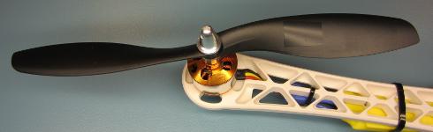
Этот шаг критически важен для стабильного полёта дрона. Если пропустить его, пропеллеры не будут стабильно работать, и дрон станет неуправляемым.
Установите пропеллеры на моторы и проверьте, что контрвесочные и часовые пропеллеры находятся в правильных позициях. Загрузите программу ESCCalibrate и откройте Serial Monitor на 57600 бод. Отправьте ‘1’ через Serial Monitor и дождитесь ответа «Test motor 1 (right front CCW)».
ESCCalibrate
//The program will start in calibration mode.
//Send the following characters / numbers via the serial monitor to change the mode
//
//r = print receiver signals.
//a = print quadcopter angles.
//1 = check rotation / vibrations for motor 1 (right front CCW).
//2 = check rotation / vibrations for motor 2 (right rear CW).
//3 = check rotation / vibrations for motor 3 (left rear CCW).
//4 = check rotation / vibrations for motor 4 (left front CW).
//5 = check vibrations for all motors together.
#include //Include the Wire.h library so we can communicate with the gyro.
#include //Include the EEPROM.h library so we can store information onto the EEPROM
//Declaring global variables
byte last_channel_1, last_channel_2, last_channel_3, last_channel_4;
byte eeprom_data[36], start, data;
boolean new_function_request,first_angle;
volatile int receiver_input_channel_1, receiver_input_channel_2, receiver_input_channel_3, receiver_input_channel_4;
int esc_1, esc_2, esc_3, esc_4;
int counter_channel_1, counter_channel_2, counter_channel_3, counter_channel_4;
int receiver_input[5];
int loop_counter, gyro_address, vibration_counter;
int temperature;
long acc_x, acc_y, acc_z, acc_total_vector[20], acc_av_vector, vibration_total_result;
unsigned long timer_channel_1, timer_channel_2, timer_channel_3, timer_channel_4, esc_timer, esc_loop_timer;
unsigned long zero_timer, timer_1, timer_2, timer_3, timer_4, current_time;
int acc_axis[4], gyro_axis[4];
double gyro_pitch, gyro_roll, gyro_yaw;
float angle_roll_acc, angle_pitch_acc, angle_pitch, angle_roll;
int cal_int;
double gyro_axis_cal[4];
//Setup routine
void setup(){
Serial.begin(9600); //Start the serial port.
Wire.begin(); //Start the wire library as master
TWBR = 12; //Set the I2C clock speed to 400kHz.
//Arduino Uno pins default to inputs, so they don't need to be explicitly declared as inputs.
DDRD |= B11110000; //Configure digital poort 4, 5, 6 and 7 as output.
DDRB |= B00010000; //Configure digital poort 12 as output.
PCICR |= (1 << PCIE0); // set PCIE0 to enable PCMSK0 scan.
PCMSK0 |= (1 << PCINT0); // set PCINT0 (digital input 8) to trigger an interrupt on state change.
PCMSK0 |= (1 << PCINT1); // set PCINT1 (digital input 9)to trigger an interrupt on state change.
PCMSK0 |= (1 << PCINT2); // set PCINT2 (digital input 10)to trigger an interrupt on state change.
PCMSK0 |= (1 << PCINT3); // set PCINT3 (digital input 11)to trigger an interrupt on state change.
for(data = 0; data <= 35; data++)eeprom_data[data] = EEPROM.read(data); //Read EEPROM for faster data access gyro_address = eeprom_data[32]; //Store the gyro address in the variable. set_gyro_registers(); //Set the specific gyro registers. //Check the EEPROM signature to make sure that the setup program is executed. while(eeprom_data[33] != 'J' || eeprom_data[34] != 'M' || eeprom_data[35] != 'B'){ delay(500); //Wait for 500ms. digitalWrite(12, !digitalRead(12)); //Change the led status to indicate error. } wait_for_receiver(); //Wait until the receiver is active. zero_timer = micros(); //Set the zero_timer for the first loop. while(Serial.available())data = Serial.read(); //Empty the serial buffer. data = 0; //Set the data variable back to zero. } //Main program loop void loop(){ while(zero_timer + 4000 > micros()); //Start the pulse after 4000 micro seconds.
zero_timer = micros(); //Reset the zero timer.
if(Serial.available() > 0){
data = Serial.read(); //Read the incomming byte.
delay(100); //Wait for any other bytes to come in
while(Serial.available() > 0)loop_counter = Serial.read(); //Empty the Serial buffer.
new_function_request = true; //Set the new request flag.
loop_counter = 0; //Reset the loop_counter variable.
cal_int = 0; //Reset the cal_int variable to undo the calibration.
start = 0; //Set start to 0.
first_angle = false; //Set first_angle to false.
//Confirm the choice on the serial monitor.
if(data == 'r')Serial.println("Reading receiver signals.");
if(data == 'a')Serial.println("Print the quadcopter angles.");
if(data == 'a')Serial.println("Gyro calibration starts in 2 seconds (don't move the quadcopter).");
if(data == '1')Serial.println("Test motor 1 (right front CCW.)");
if(data == '2')Serial.println("Test motor 2 (right rear CW.)");
if(data == '3')Serial.println("Test motor 3 (left rear CCW.)");
if(data == '4')Serial.println("Test motor 4 (left front CW.)");
if(data == '5')Serial.println("Test all motors together");
//Let's create a small delay so the message stays visible for 2.5 seconds.
//We don't want the ESC's to beep and have to send a 1000us pulse to the ESC's.
for(vibration_counter = 0; vibration_counter < 625; vibration_counter++){ //Do this loop 625 times
delay(3); //Wait 3000us.
esc_1 = 1000; //Set the pulse for ESC 1 to 1000us.
esc_2 = 1000; //Set the pulse for ESC 1 to 1000us.
esc_3 = 1000; //Set the pulse for ESC 1 to 1000us.
esc_4 = 1000; //Set the pulse for ESC 1 to 1000us.
esc_pulse_output(); //Send the ESC control pulses.
}
vibration_counter = 0; //Reset the vibration_counter variable.
}
receiver_input_channel_3 = convert_receiver_channel(3); //Convert the actual receiver signals for throttle to the standard 1000 - 2000us.
if(receiver_input_channel_3 < 1025)new_function_request = false; //If the throttle is in the lowest position set the request flag to false.
////////////////////////////////////////////////////////////////////////////////////////////
//Run the ESC calibration program to start with.
////////////////////////////////////////////////////////////////////////////////////////////
if(data == 0 && new_function_request == false){ //Only start the calibration mode at first start.
receiver_input_channel_3 = convert_receiver_channel(3); //Convert the actual receiver signals for throttle to the standard 1000 - 2000us.
esc_1 = receiver_input_channel_3; //Set the pulse for motor 1 equal to the throttle channel.
esc_2 = receiver_input_channel_3; //Set the pulse for motor 2 equal to the throttle channel.
esc_3 = receiver_input_channel_3; //Set the pulse for motor 3 equal to the throttle channel.
esc_4 = receiver_input_channel_3; //Set the pulse for motor 4 equal to the throttle channel.
esc_pulse_output(); //Send the ESC control pulses.
}
////////////////////////////////////////////////////////////////////////////////////////////
//When user sends a 'r' print the receiver signals.
////////////////////////////////////////////////////////////////////////////////////////////
if(data == 'r'){
loop_counter ++; //Increase the loop_counter variable.
receiver_input_channel_1 = convert_receiver_channel(1); //Convert the actual receiver signals for pitch to the standard 1000 - 2000us.
receiver_input_channel_2 = convert_receiver_channel(2); //Convert the actual receiver signals for roll to the standard 1000 - 2000us.
receiver_input_channel_3 = convert_receiver_channel(3); //Convert the actual receiver signals for throttle to the standard 1000 - 2000us.
receiver_input_channel_4 = convert_receiver_channel(4); //Convert the actual receiver signals for yaw to the standard 1000 - 2000us.
if(loop_counter == 125){ //Print the receiver values when the loop_counter variable equals 250.
print_signals(); //Print the receiver values on the serial monitor.
loop_counter = 0; //Reset the loop_counter variable.
}
//For starting the motors: throttle low and yaw left (step 1).
if(receiver_input_channel_3 < 1050 && receiver_input_channel_4 < 1050)start = 1;
//When yaw stick is back in the center position start the motors (step 2).
if(start == 1 && receiver_input_channel_3 < 1050 && receiver_input_channel_4 > 1450)start = 2;
//Stopping the motors: throttle low and yaw right.
if(start == 2 && receiver_input_channel_3 < 1050 && receiver_input_channel_4 > 1950)start = 0;
esc_1 = 1000; //Set the pulse for ESC 1 to 1000us.
esc_2 = 1000; //Set the pulse for ESC 1 to 1000us.
esc_3 = 1000; //Set the pulse for ESC 1 to 1000us.
esc_4 = 1000; //Set the pulse for ESC 1 to 1000us.
esc_pulse_output(); //Send the ESC control pulses.
}
///////////////////////////////////////////////////////////////////////////////////////////
//When user sends a '1, 2, 3, 4 or 5 test the motors.
////////////////////////////////////////////////////////////////////////////////////////////
if(data == '1' || data == '2' || data == '3' || data == '4' || data == '5'){ //If motor 1, 2, 3 or 4 is selected by the user.
loop_counter ++; //Add 1 to the loop_counter variable.
if(new_function_request == true && loop_counter == 250){ //Wait for the throttle to be set to 0.
Serial.print("Set throttle to 1000 (low). It's now set to: "); //Print message on the serial monitor.
Serial.println(receiver_input_channel_3); //Print the actual throttle position.
loop_counter = 0; //Reset the loop_counter variable.
}
if(new_function_request == false){ //When the throttle was in the lowest position do this.
receiver_input_channel_3 = convert_receiver_channel(3); //Convert the actual receiver signals for throttle to the standard 1000 - 2000us.
if(data == '1' || data == '5')esc_1 = receiver_input_channel_3; //If motor 1 is requested set the pulse for motor 1 equal to the throttle channel.
else esc_1 = 1000; //If motor 1 is not requested set the pulse for the ESC to 1000us (off).
if(data == '2' || data == '5')esc_2 = receiver_input_channel_3; //If motor 2 is requested set the pulse for motor 1 equal to the throttle channel.
else esc_2 = 1000; //If motor 2 is not requested set the pulse for the ESC to 1000us (off).
if(data == '3' || data == '5')esc_3 = receiver_input_channel_3; //If motor 3 is requested set the pulse for motor 1 equal to the throttle channel.
else esc_3 = 1000; //If motor 3 is not requested set the pulse for the ESC to 1000us (off).
if(data == '4' || data == '5')esc_4 = receiver_input_channel_3; //If motor 4 is requested set the pulse for motor 1 equal to the throttle channel.
else esc_4 = 1000; //If motor 4 is not requested set the pulse for the ESC to 1000us (off).
esc_pulse_output(); //Send the ESC control pulses.
//For balancing the propellors it's possible to use the accelerometer to measure the vibrations.
if(eeprom_data[31] == 1){ //The MPU-6050 is installed
Wire.beginTransmission(gyro_address); //Start communication with the gyro.
Wire.write(0x3B); //Start reading @ register 43h and auto increment with every read.
Wire.endTransmission(); //End the transmission.
Wire.requestFrom(gyro_address,6); //Request 6 bytes from the gyro.
while(Wire.available() < 6); //Wait until the 6 bytes are received.
acc_x = Wire.read()<<8|Wire.read(); //Add the low and high byte to the acc_x variable.
acc_y = Wire.read()<<8|Wire.read(); //Add the low and high byte to the acc_y variable.
acc_z = Wire.read()<<8|Wire.read(); //Add the low and high byte to the acc_z variable. acc_total_vector[0] = sqrt((acc_x*acc_x)+(acc_y*acc_y)+(acc_z*acc_z)); //Calculate the total accelerometer vector. acc_av_vector = acc_total_vector[0]; //Copy the total vector to the accelerometer average vector variable. for(start = 16; start > 0; start--){ //Do this loop 16 times to create an array of accelrometer vectors.
acc_total_vector[start] = acc_total_vector[start - 1]; //Shift every variable one position up in the array.
acc_av_vector += acc_total_vector[start]; //Add the array value to the acc_av_vector variable.
}
acc_av_vector /= 17; //Divide the acc_av_vector by 17 to get the avarage total accelerometer vector.
if(vibration_counter < 20){ //If the vibration_counter is less than 20 do this.
vibration_counter ++; //Increment the vibration_counter variable.
vibration_total_result += abs(acc_total_vector[0] - acc_av_vector); //Add the absolute difference between the avarage vector and current vector to the vibration_total_result variable.
}
else{
vibration_counter = 0; //If the vibration_counter is equal or larger than 20 do this.
Serial.println(vibration_total_result/50); //Print the total accelerometer vector divided by 50 on the serial monitor.
vibration_total_result = 0; //Reset the vibration_total_result variable.
}
}
}
}
///////////////////////////////////////////////////////////////////////////////////////////
//When user sends a 'a' display the quadcopter angles.
////////////////////////////////////////////////////////////////////////////////////////////
if(data == 'a'){
if(cal_int != 2000){
Serial.print("Calibrating the gyro");
//Let's take multiple gyro data samples so we can determine the average gyro offset (calibration).
for (cal_int = 0; cal_int < 2000 ; cal_int ++){ //Take 2000 readings for calibration.
if(cal_int % 125 == 0){
digitalWrite(12, !digitalRead(12)); //Change the led status to indicate calibration.
Serial.print(".");
}
gyro_signalen(); //Read the gyro output.
gyro_axis_cal[1] += gyro_axis[1]; //Ad roll value to gyro_roll_cal.
gyro_axis_cal[2] += gyro_axis[2]; //Ad pitch value to gyro_pitch_cal.
gyro_axis_cal[3] += gyro_axis[3]; //Ad yaw value to gyro_yaw_cal.
//We don't want the esc's to be beeping annoyingly. So let's give them a 1000us puls while calibrating the gyro.
PORTD |= B11110000; //Set digital poort 4, 5, 6 and 7 high.
delayMicroseconds(1000); //Wait 1000us.
PORTD &= B00001111; //Set digital poort 4, 5, 6 and 7 low.
delay(3); //Wait 3 milliseconds before the next loop.
}
Serial.println(".");
//Now that we have 2000 measures, we need to devide by 2000 to get the average gyro offset.
gyro_axis_cal[1] /= 2000; //Divide the roll total by 2000.
gyro_axis_cal[2] /= 2000; //Divide the pitch total by 2000.
gyro_axis_cal[3] /= 2000; //Divide the yaw total by 2000.
}
else{
///We don't want the esc's to be beeping annoyingly. So let's give them a 1000us puls while calibrating the gyro.
PORTD |= B11110000; //Set digital poort 4, 5, 6 and 7 high.
delayMicroseconds(1000); //Wait 1000us.
PORTD &= B00001111; //Set digital poort 4, 5, 6 and 7 low.
//Let's get the current gyro data.
gyro_signalen();
//Gyro angle calculations
//0.0000611 = 1 / (250Hz / 65.5)
angle_pitch += gyro_pitch * 0.0000611; //Calculate the traveled pitch angle and add this to the angle_pitch variable.
angle_roll += gyro_roll * 0.0000611; //Calculate the traveled roll angle and add this to the angle_roll variable.
//0.000001066 = 0.0000611 * (3.142(PI) / 180degr) The Arduino sin function is in radians
angle_pitch -= angle_roll * sin(gyro_yaw * 0.000001066); //If the IMU has yawed transfer the roll angle to the pitch angel.
angle_roll += angle_pitch * sin(gyro_yaw * 0.000001066); //If the IMU has yawed transfer the pitch angle to the roll angel.
//Accelerometer angle calculations
acc_total_vector[0] = sqrt((acc_x*acc_x)+(acc_y*acc_y)+(acc_z*acc_z)); //Calculate the total accelerometer vector.
//57.296 = 1 / (3.142 / 180) The Arduino asin function is in radians
angle_pitch_acc = asin((float)acc_y/acc_total_vector[0])* 57.296; //Calculate the pitch angle.
angle_roll_acc = asin((float)acc_x/acc_total_vector[0])* -57.296; //Calculate the roll angle.
if(!first_angle){
angle_pitch = angle_pitch_acc; //Set the pitch angle to the accelerometer angle.
angle_roll = angle_roll_acc; //Set the roll angle to the accelerometer angle.
first_angle = true;
}
else{
angle_pitch = angle_pitch * 0.9996 + angle_pitch_acc * 0.0004; //Correct the drift of the gyro pitch angle with the accelerometer pitch angle.
angle_roll = angle_roll * 0.9996 + angle_roll_acc * 0.0004; //Correct the drift of the gyro roll angle with the accelerometer roll angle.
}
//We can't print all the data at once. This takes to long and the angular readings will be off.
if(loop_counter == 0)Serial.print("Pitch: ");
if(loop_counter == 1)Serial.print(angle_pitch ,0);
if(loop_counter == 2)Serial.print(" Roll: ");
if(loop_counter == 3)Serial.print(angle_roll ,0);
if(loop_counter == 4)Serial.print(" Yaw: ");
if(loop_counter == 5)Serial.println(gyro_yaw / 65.5 ,0);
loop_counter ++;
if(loop_counter == 60)loop_counter = 0;
}
}
}
//This routine is called every time input 8, 9, 10 or 11 changed state.
ISR(PCINT0_vect){
current_time = micros();
//Channel 1=========================================
if(PINB & B00000001){ //Is input 8 high?
if(last_channel_1 == 0){ //Input 8 changed from 0 to 1.
last_channel_1 = 1; //Remember current input state.
timer_1 = current_time; //Set timer_1 to current_time.
}
}
else if(last_channel_1 == 1){ //Input 8 is not high and changed from 1 to 0.
last_channel_1 = 0; //Remember current input state.
receiver_input[1] = current_time - timer_1; //Channel 1 is current_time - timer_1.
}
//Channel 2=========================================
if(PINB & B00000010 ){ //Is input 9 high?
if(last_channel_2 == 0){ //Input 9 changed from 0 to 1.
last_channel_2 = 1; //Remember current input state.
timer_2 = current_time; //Set timer_2 to current_time.
}
}
else if(last_channel_2 == 1){ //Input 9 is not high and changed from 1 to 0.
last_channel_2 = 0; //Remember current input state.
receiver_input[2] = current_time - timer_2; //Channel 2 is current_time - timer_2.
}
//Channel 3=========================================
if(PINB & B00000100 ){ //Is input 10 high?
if(last_channel_3 == 0){ //Input 10 changed from 0 to 1.
last_channel_3 = 1; //Remember current input state.
timer_3 = current_time; //Set timer_3 to current_time.
}
}
else if(last_channel_3 == 1){ //Input 10 is not high and changed from 1 to 0.
last_channel_3 = 0; //Remember current input state.
receiver_input[3] = current_time - timer_3; //Channel 3 is current_time - timer_3.
}
//Channel 4=========================================
if(PINB & B00001000 ){ //Is input 11 high?
if(last_channel_4 == 0){ //Input 11 changed from 0 to 1.
last_channel_4 = 1; //Remember current input state.
timer_4 = current_time; //Set timer_4 to current_time.
}
}
else if(last_channel_4 == 1){ //Input 11 is not high and changed from 1 to 0.
last_channel_4 = 0; //Remember current input state.
receiver_input[4] = current_time - timer_4; //Channel 4 is current_time - timer_4.
}
}
//Checck if the receiver values are valid within 10 seconds
void wait_for_receiver(){
byte zero = 0; //Set all bits in the variable zero to 0
while(zero < 15){ //Stay in this loop until the 4 lowest bits are set
if(receiver_input[1] < 2100 && receiver_input[1] > 900)zero |= 0b00000001; //Set bit 0 if the receiver pulse 1 is within the 900 - 2100 range
if(receiver_input[2] < 2100 && receiver_input[2] > 900)zero |= 0b00000010; //Set bit 1 if the receiver pulse 2 is within the 900 - 2100 range
if(receiver_input[3] < 2100 && receiver_input[3] > 900)zero |= 0b00000100; //Set bit 2 if the receiver pulse 3 is within the 900 - 2100 range
if(receiver_input[4] < 2100 && receiver_input[4] > 900)zero |= 0b00001000; //Set bit 3 if the receiver pulse 4 is within the 900 - 2100 range
delay(500); //Wait 500 milliseconds
}
}
//This part converts the actual receiver signals to a standardized 1000 – 1500 – 2000 microsecond value.
//The stored data in the EEPROM is used.
int convert_receiver_channel(byte function){
byte channel, reverse; //First we declare some local variables
int low, center, high, actual;
int difference;
channel = eeprom_data[function + 23] & 0b00000111; //What channel corresponds with the specific function
if(eeprom_data[function + 23] & 0b10000000)reverse = 1; //Reverse channel when most significant bit is set
else reverse = 0; //If the most significant is not set there is no reverse
actual = receiver_input[channel]; //Read the actual receiver value for the corresponding function
low = (eeprom_data[channel * 2 + 15] << 8) | eeprom_data[channel * 2 + 14]; //Store the low value for the specific receiver input channel
center = (eeprom_data[channel * 2 - 1] << 8) | eeprom_data[channel * 2 - 2]; //Store the center value for the specific receiver input channel
high = (eeprom_data[channel * 2 + 7] << 8) | eeprom_data[channel * 2 + 6]; //Store the high value for the specific receiver input channel
if(actual < center){ //The actual receiver value is lower than the center value
if(actual < low)actual = low; //Limit the lowest value to the value that was detected during setup difference = ((long)(center - actual) * (long)500) / (center - low); //Calculate and scale the actual value to a 1000 - 2000us value if(reverse == 1)return 1500 + difference; //If the channel is reversed else return 1500 - difference; //If the channel is not reversed } else if(actual > center){ //The actual receiver value is higher than the center value
if(actual > high)actual = high; //Limit the lowest value to the value that was detected during setup
difference = ((long)(actual - center) * (long)500) / (high - center); //Calculate and scale the actual value to a 1000 - 2000us value
if(reverse == 1)return 1500 - difference; //If the channel is reversed
else return 1500 + difference; //If the channel is not reversed
}
else return 1500;
}
void print_signals(){
Serial.print("Start:");
Serial.print(start);
Serial.print(" Roll:");
if(receiver_input_channel_1 - 1480 < 0)Serial.print("<<<"); else if(receiver_input_channel_1 - 1520 > 0)Serial.print(">>>");
else Serial.print("-+-");
Serial.print(receiver_input_channel_1);
Serial.print(" Pitch:");
if(receiver_input_channel_2 - 1480 < 0)Serial.print("^^^"); else if(receiver_input_channel_2 - 1520 > 0)Serial.print("vvv");
else Serial.print("-+-");
Serial.print(receiver_input_channel_2);
Serial.print(" Throttle:");
if(receiver_input_channel_3 - 1480 < 0)Serial.print("vvv"); else if(receiver_input_channel_3 - 1520 > 0)Serial.print("^^^");
else Serial.print("-+-");
Serial.print(receiver_input_channel_3);
Serial.print(" Yaw:");
if(receiver_input_channel_4 - 1480 < 0)Serial.print("<<<"); else if(receiver_input_channel_4 - 1520 > 0)Serial.print(">>>");
else Serial.print("-+-");
Serial.println(receiver_input_channel_4);
}
void esc_pulse_output(){
zero_timer = micros();
PORTD |= B11110000; //Set port 4, 5, 6 and 7 high at once
timer_channel_1 = esc_1 + zero_timer; //Calculate the time when digital port 4 is set low.
timer_channel_2 = esc_2 + zero_timer; //Calculate the time when digital port 5 is set low.
timer_channel_3 = esc_3 + zero_timer; //Calculate the time when digital port 6 is set low.
timer_channel_4 = esc_4 + zero_timer; //Calculate the time when digital port 7 is set low.
while(PORTD >= 16){ //Execute the loop until digital port 4 to 7 is low.
esc_loop_timer = micros(); //Check the current time.
if(timer_channel_1 <= esc_loop_timer)PORTD &= B11101111; //When the delay time is expired, digital port 4 is set low.
if(timer_channel_2 <= esc_loop_timer)PORTD &= B11011111; //When the delay time is expired, digital port 5 is set low.
if(timer_channel_3 <= esc_loop_timer)PORTD &= B10111111; //When the delay time is expired, digital port 6 is set low.
if(timer_channel_4 <= esc_loop_timer)PORTD &= B01111111; //When the delay time is expired, digital port 7 is set low.
}
}
void set_gyro_registers(){
//Setup the MPU-6050
if(eeprom_data[31] == 1){
Wire.beginTransmission(gyro_address); //Start communication with the address found during search.
Wire.write(0x6B); //We want to write to the PWR_MGMT_1 register (6B hex)
Wire.write(0x00); //Set the register bits as 00000000 to activate the gyro
Wire.endTransmission(); //End the transmission with the gyro.
Wire.beginTransmission(gyro_address); //Start communication with the address found during search.
Wire.write(0x1B); //We want to write to the GYRO_CONFIG register (1B hex)
Wire.write(0x08); //Set the register bits as 00001000 (500dps full scale)
Wire.endTransmission(); //End the transmission with the gyro
Wire.beginTransmission(gyro_address); //Start communication with the address found during search.
Wire.write(0x1C); //We want to write to the ACCEL_CONFIG register (1A hex)
Wire.write(0x10); //Set the register bits as 00010000 (+/- 8g full scale range)
Wire.endTransmission(); //End the transmission with the gyro
//Let's perform a random register check to see if the values are written correct
Wire.beginTransmission(gyro_address); //Start communication with the address found during search
Wire.write(0x1B); //Start reading @ register 0x1B
Wire.endTransmission(); //End the transmission
Wire.requestFrom(gyro_address, 1); //Request 1 bytes from the gyro
while(Wire.available() < 1); //Wait until the 6 bytes are received
if(Wire.read() != 0x08){ //Check if the value is 0x08
digitalWrite(12,HIGH); //Turn on the warning led
while(1)delay(10); //Stay in this loop for ever
}
Wire.beginTransmission(gyro_address); //Start communication with the address found during search
Wire.write(0x1A); //We want to write to the CONFIG register (1A hex)
Wire.write(0x03); //Set the register bits as 00000011 (Set Digital Low Pass Filter to ~43Hz)
Wire.endTransmission(); //End the transmission with the gyro
}
}
void gyro_signalen(){
//Read the MPU-6050
if(eeprom_data[31] == 1){
Wire.beginTransmission(gyro_address); //Start communication with the gyro.
Wire.write(0x3B); //Start reading @ register 43h and auto increment with every read.
Wire.endTransmission(); //End the transmission.
Wire.requestFrom(gyro_address,14); //Request 14 bytes from the gyro.
while(Wire.available() < 14); //Wait until the 14 bytes are received.
acc_axis[1] = Wire.read()<<8|Wire.read(); //Add the low and high byte to the acc_x variable.
acc_axis[2] = Wire.read()<<8|Wire.read(); //Add the low and high byte to the acc_y variable.
acc_axis[3] = Wire.read()<<8|Wire.read(); //Add the low and high byte to the acc_z variable.
temperature = Wire.read()<<8|Wire.read(); //Add the low and high byte to the temperature variable.
gyro_axis[1] = Wire.read()<<8|Wire.read(); //Read high and low part of the angular data.
gyro_axis[2] = Wire.read()<<8|Wire.read(); //Read high and low part of the angular data.
gyro_axis[3] = Wire.read()<<8|Wire.read(); //Read high and low part of the angular data.
}
if(cal_int == 2000){
gyro_axis[1] -= gyro_axis_cal[1]; //Only compensate after the calibration.
gyro_axis[2] -= gyro_axis_cal[2]; //Only compensate after the calibration.
gyro_axis[3] -= gyro_axis_cal[3]; //Only compensate after the calibration.
}
gyro_roll = gyro_axis[eeprom_data[28] & 0b00000011]; //Set gyro_roll to the correct axis that was stored in the EEPROM.
if(eeprom_data[28] & 0b10000000)gyro_roll *= -1; //Invert gyro_roll if the MSB of EEPROM bit 28 is set.
gyro_pitch = gyro_axis[eeprom_data[29] & 0b00000011]; //Set gyro_pitch to the correct axis that was stored in the EEPROM.
if(eeprom_data[29] & 0b10000000)gyro_pitch *= -1; //Invert gyro_pitch if the MSB of EEPROM bit 29 is set.
gyro_yaw = gyro_axis[eeprom_data[30] & 0b00000011]; //Set gyro_yaw to the correct axis that was stored in the EEPROM.
if(eeprom_data[30] & 0b10000000)gyro_yaw *= -1; //Invert gyro_yaw if the MSB of EEPROM bit 30 is set.
acc_x = acc_axis[eeprom_data[29] & 0b00000011]; //Set acc_x to the correct axis that was stored in the EEPROM.
if(eeprom_data[29] & 0b10000000)acc_x *= -1; //Invert acc_x if the MSB of EEPROM bit 29 is set.
acc_y = acc_axis[eeprom_data[28] & 0b00000011]; //Set acc_y to the correct axis that was stored in the EEPROM.
if(eeprom_data[28] & 0b10000000)acc_y *= -1; //Invert acc_y if the MSB of EEPROM bit 28 is set.
acc_z = acc_axis[eeprom_data[30] & 0b00000011]; //Set acc_z to the correct axis that was stored in the EEPROM.
if(eeprom_data[30] & 0b10000000)acc_z *= -1; //Invert acc_z if the MSB of EEPROM bit 30 is set.
}Числа на экране представляют собой количество вибраций, измеренных акселерометром. Держите раму мотора крепко в руках и увеличивайте дроссель до половины. Проверьте числа на экране и запомните вибрации, которые ощущаете рукой.
Шаг 6: Программирование дрона. Часть 2
Этот шаг легко выполнить. Скачайте скетч FlightController и загрузите его в дрон. Затем отключите дрон и подключите аккумулятор. Вы должны услышать серию звуков «Beep beep beep BEEEEP!». Если слышите этот набор, всё в порядке. Если нет, значит, вы неправильно очистили EEPROM.
FlightController
#include //Include the Wire.h library so we can communicate with the gyro.
#include //Include the EEPROM.h library so we can store information onto the EEPROM
///////////////////////////////////////////////////////////////////////////////////////////////////////////////////////////////////////
//PID gain and limit settings
///////////////////////////////////////////////////////////////////////////////////////////////////////////////////////////////////////
float pid_p_gain_roll = 1.3; //Gain setting for the roll P-controller
float pid_i_gain_roll = 0.04; //Gain setting for the roll I-controller
float pid_d_gain_roll = 18.0; //Gain setting for the roll D-controller
int pid_max_roll = 400; //Maximum output of the PID-controller (+/-)
float pid_p_gain_pitch = pid_p_gain_roll; //Gain setting for the pitch P-controller.
float pid_i_gain_pitch = pid_i_gain_roll; //Gain setting for the pitch I-controller.
float pid_d_gain_pitch = pid_d_gain_roll; //Gain setting for the pitch D-controller.
int pid_max_pitch = pid_max_roll; //Maximum output of the PID-controller (+/-)
float pid_p_gain_yaw = 4.0; //Gain setting for the pitch P-controller. //4.0
float pid_i_gain_yaw = 0.02; //Gain setting for the pitch I-controller. //0.02
float pid_d_gain_yaw = 0.0; //Gain setting for the pitch D-controller.
int pid_max_yaw = 400; //Maximum output of the PID-controller (+/-)
boolean auto_level = true; //Auto level on (true) or off (false)
///////////////////////////////////////////////////////////////////////////////////////////////////////////////////////////////////////
//Declaring global variables
///////////////////////////////////////////////////////////////////////////////////////////////////////////////////////////////////////
byte last_channel_1, last_channel_2, last_channel_3, last_channel_4;
byte eeprom_data[36];
byte highByte, lowByte;
volatile int receiver_input_channel_1, receiver_input_channel_2, receiver_input_channel_3, receiver_input_channel_4;
int counter_channel_1, counter_channel_2, counter_channel_3, counter_channel_4, loop_counter;
int esc_1, esc_2, esc_3, esc_4;
int throttle, battery_voltage;
int cal_int, start, gyro_address;
int receiver_input[5];
int temperature;
int acc_axis[4], gyro_axis[4];
float roll_level_adjust, pitch_level_adjust;
long acc_x, acc_y, acc_z, acc_total_vector;
unsigned long timer_channel_1, timer_channel_2, timer_channel_3, timer_channel_4, esc_timer, esc_loop_timer;
unsigned long timer_1, timer_2, timer_3, timer_4, current_time;
unsigned long loop_timer;
double gyro_pitch, gyro_roll, gyro_yaw;
double gyro_axis_cal[4];
float pid_error_temp;
float pid_i_mem_roll, pid_roll_setpoint, gyro_roll_input, pid_output_roll, pid_last_roll_d_error;
float pid_i_mem_pitch, pid_pitch_setpoint, gyro_pitch_input, pid_output_pitch, pid_last_pitch_d_error;
float pid_i_mem_yaw, pid_yaw_setpoint, gyro_yaw_input, pid_output_yaw, pid_last_yaw_d_error;
float angle_roll_acc, angle_pitch_acc, angle_pitch, angle_roll;
boolean gyro_angles_set;
///////////////////////////////////////////////////////////////////////////////////////////////////////////////////////////////////////
//Setup routine
///////////////////////////////////////////////////////////////////////////////////////////////////////////////////////////////////////
void setup(){
//Serial.begin(57600);
//Copy the EEPROM data for fast access data.
for(start = 0; start <= 35; start++)eeprom_data[start] = EEPROM.read(start);
start = 0; //Set start back to zero.
gyro_address = eeprom_data[32]; //Store the gyro address in the variable.
Wire.begin(); //Start the I2C as master.
TWBR = 12; //Set the I2C clock speed to 400kHz.
//Arduino (Atmega) pins default to inputs, so they don't need to be explicitly declared as inputs.
DDRD |= B11110000; //Configure digital poort 4, 5, 6 and 7 as output.
DDRB |= B00110000; //Configure digital poort 12 and 13 as output.
//Use the led on the Arduino for startup indication.
digitalWrite(12,HIGH); //Turn on the warning led.
//Check the EEPROM signature to make sure that the setup program is executed.
while(eeprom_data[33] != 'J' || eeprom_data[34] != 'M' || eeprom_data[35] != 'B')delay(10);
//The flight controller needs the MPU-6050 with gyro and accelerometer
//If setup is completed without MPU-6050 stop the flight controller program
if(eeprom_data[31] == 2 || eeprom_data[31] == 3)delay(10);
set_gyro_registers(); //Set the specific gyro registers.
for (cal_int = 0; cal_int < 1250 ; cal_int ++){ //Wait 5 seconds before continuing.
PORTD |= B11110000; //Set digital poort 4, 5, 6 and 7 high.
delayMicroseconds(1000); //Wait 1000us.
PORTD &= B00001111; //Set digital poort 4, 5, 6 and 7 low.
delayMicroseconds(3000); //Wait 3000us.
}
//Let's take multiple gyro data samples so we can determine the average gyro offset (calibration).
for (cal_int = 0; cal_int < 2000 ; cal_int ++){ //Take 2000 readings for calibration.
if(cal_int % 15 == 0)digitalWrite(12, !digitalRead(12)); //Change the led status to indicate calibration.
gyro_signalen(); //Read the gyro output.
gyro_axis_cal[1] += gyro_axis[1]; //Ad roll value to gyro_roll_cal.
gyro_axis_cal[2] += gyro_axis[2]; //Ad pitch value to gyro_pitch_cal.
gyro_axis_cal[3] += gyro_axis[3]; //Ad yaw value to gyro_yaw_cal.
//We don't want the esc's to be beeping annoyingly. So let's give them a 1000us puls while calibrating the gyro.
PORTD |= B11110000; //Set digital poort 4, 5, 6 and 7 high.
delayMicroseconds(1000); //Wait 1000us.
PORTD &= B00001111; //Set digital poort 4, 5, 6 and 7 low.
delay(3); //Wait 3 milliseconds before the next loop.
}
//Now that we have 2000 measures, we need to devide by 2000 to get the average gyro offset.
gyro_axis_cal[1] /= 2000; //Divide the roll total by 2000.
gyro_axis_cal[2] /= 2000; //Divide the pitch total by 2000.
gyro_axis_cal[3] /= 2000; //Divide the yaw total by 2000.
PCICR |= (1 << PCIE0); //Set PCIE0 to enable PCMSK0 scan.
PCMSK0 |= (1 << PCINT0); //Set PCINT0 (digital input 8) to trigger an interrupt on state change.
PCMSK0 |= (1 << PCINT1); //Set PCINT1 (digital input 9)to trigger an interrupt on state change.
PCMSK0 |= (1 << PCINT2); //Set PCINT2 (digital input 10)to trigger an interrupt on state change.
PCMSK0 |= (1 << PCINT3); //Set PCINT3 (digital input 11)to trigger an interrupt on state change.
//Wait until the receiver is active and the throtle is set to the lower position.
while(receiver_input_channel_3 < 990 || receiver_input_channel_3 > 1020 || receiver_input_channel_4 < 1400){
receiver_input_channel_3 = convert_receiver_channel(3); //Convert the actual receiver signals for throttle to the standard 1000 - 2000us
receiver_input_channel_4 = convert_receiver_channel(4); //Convert the actual receiver signals for yaw to the standard 1000 - 2000us
start ++; //While waiting increment start whith every loop.
//We don't want the esc's to be beeping annoyingly. So let's give them a 1000us puls while waiting for the receiver inputs.
PORTD |= B11110000; //Set digital poort 4, 5, 6 and 7 high.
delayMicroseconds(1000); //Wait 1000us.
PORTD &= B00001111; //Set digital poort 4, 5, 6 and 7 low.
delay(3); //Wait 3 milliseconds before the next loop.
if(start == 125){ //Every 125 loops (500ms).
digitalWrite(12, !digitalRead(12)); //Change the led status.
start = 0; //Start again at 0.
}
}
start = 0; //Set start back to 0.
//Load the battery voltage to the battery_voltage variable.
//65 is the voltage compensation for the diode.
//12.6V equals ~5V @ Analog 0.
//12.6V equals 1023 analogRead(0).
//1260 / 1023 = 1.2317.
//The variable battery_voltage holds 1050 if the battery voltage is 10.5V.
battery_voltage = (analogRead(0) + 65) * 1.2317;
loop_timer = micros(); //Set the timer for the next loop.
//When everything is done, turn off the led.
digitalWrite(12,LOW); //Turn off the warning led.
}
///////////////////////////////////////////////////////////////////////////////////////////////////////////////////////////////////////
//Main program loop
///////////////////////////////////////////////////////////////////////////////////////////////////////////////////////////////////////
void loop(){
//65.5 = 1 deg/sec (check the datasheet of the MPU-6050 for more information).
gyro_roll_input = (gyro_roll_input * 0.7) + ((gyro_roll / 65.5) * 0.3); //Gyro pid input is deg/sec.
gyro_pitch_input = (gyro_pitch_input * 0.7) + ((gyro_pitch / 65.5) * 0.3);//Gyro pid input is deg/sec.
gyro_yaw_input = (gyro_yaw_input * 0.7) + ((gyro_yaw / 65.5) * 0.3); //Gyro pid input is deg/sec.
//Gyro angle calculations
//0.0000611 = 1 / (250Hz / 65.5)
angle_pitch += gyro_pitch * 0.0000611; //Calculate the traveled pitch angle and add this to the angle_pitch variable.
angle_roll += gyro_roll * 0.0000611; //Calculate the traveled roll angle and add this to the angle_roll variable.
//0.000001066 = 0.0000611 * (3.142(PI) / 180degr) The Arduino sin function is in radians
angle_pitch -= angle_roll * sin(gyro_yaw * 0.000001066); //If the IMU has yawed transfer the roll angle to the pitch angel.
angle_roll += angle_pitch * sin(gyro_yaw * 0.000001066); //If the IMU has yawed transfer the pitch angle to the roll angel.
//Accelerometer angle calculations
acc_total_vector = sqrt((acc_x*acc_x)+(acc_y*acc_y)+(acc_z*acc_z)); //Calculate the total accelerometer vector.
if(abs(acc_y) < acc_total_vector){ //Prevent the asin function to produce a NaN
angle_pitch_acc = asin((float)acc_y/acc_total_vector)* 57.296; //Calculate the pitch angle.
}
if(abs(acc_x) < acc_total_vector){ //Prevent the asin function to produce a NaN
angle_roll_acc = asin((float)acc_x/acc_total_vector)* -57.296; //Calculate the roll angle.
}
//Place the MPU-6050 spirit level and note the values in the following two lines for calibration.
angle_pitch_acc -= 0.0; //Accelerometer calibration value for pitch.
angle_roll_acc -= 0.0; //Accelerometer calibration value for roll.
angle_pitch = angle_pitch * 0.9996 + angle_pitch_acc * 0.0004; //Correct the drift of the gyro pitch angle with the accelerometer pitch angle.
angle_roll = angle_roll * 0.9996 + angle_roll_acc * 0.0004; //Correct the drift of the gyro roll angle with the accelerometer roll angle.
pitch_level_adjust = angle_pitch * 15; //Calculate the pitch angle correction
roll_level_adjust = angle_roll * 15; //Calculate the roll angle correction
if(!auto_level){ //If the quadcopter is not in auto-level mode
pitch_level_adjust = 0; //Set the pitch angle correction to zero.
roll_level_adjust = 0; //Set the roll angle correcion to zero.
}
//For starting the motors: throttle low and yaw left (step 1).
if(receiver_input_channel_3 < 1050 && receiver_input_channel_4 < 1050)start = 1;
//When yaw stick is back in the center position start the motors (step 2).
if(start == 1 && receiver_input_channel_3 < 1050 && receiver_input_channel_4 > 1450){
start = 2;
angle_pitch = angle_pitch_acc; //Set the gyro pitch angle equal to the accelerometer pitch angle when the quadcopter is started.
angle_roll = angle_roll_acc; //Set the gyro roll angle equal to the accelerometer roll angle when the quadcopter is started.
gyro_angles_set = true; //Set the IMU started flag.
//Reset the PID controllers for a bumpless start.
pid_i_mem_roll = 0;
pid_last_roll_d_error = 0;
pid_i_mem_pitch = 0;
pid_last_pitch_d_error = 0;
pid_i_mem_yaw = 0;
pid_last_yaw_d_error = 0;
}
//Stopping the motors: throttle low and yaw right.
if(start == 2 && receiver_input_channel_3 < 1050 && receiver_input_channel_4 > 1950)start = 0;
//The PID set point in degrees per second is determined by the roll receiver input.
//In the case of deviding by 3 the max roll rate is aprox 164 degrees per second ( (500-8)/3 = 164d/s ).
pid_roll_setpoint = 0;
//We need a little dead band of 16us for better results.
if(receiver_input_channel_1 > 1508)pid_roll_setpoint = receiver_input_channel_1 - 1508;
else if(receiver_input_channel_1 < 1492)pid_roll_setpoint = receiver_input_channel_1 - 1492; pid_roll_setpoint -= roll_level_adjust; //Subtract the angle correction from the standardized receiver roll input value. pid_roll_setpoint /= 3.0; //Divide the setpoint for the PID roll controller by 3 to get angles in degrees. //The PID set point in degrees per second is determined by the pitch receiver input. //In the case of deviding by 3 the max pitch rate is aprox 164 degrees per second ( (500-8)/3 = 164d/s ). pid_pitch_setpoint = 0; //We need a little dead band of 16us for better results. if(receiver_input_channel_2 > 1508)pid_pitch_setpoint = receiver_input_channel_2 - 1508;
else if(receiver_input_channel_2 < 1492)pid_pitch_setpoint = receiver_input_channel_2 - 1492; pid_pitch_setpoint -= pitch_level_adjust; //Subtract the angle correction from the standardized receiver pitch input value. pid_pitch_setpoint /= 3.0; //Divide the setpoint for the PID pitch controller by 3 to get angles in degrees. //The PID set point in degrees per second is determined by the yaw receiver input. //In the case of deviding by 3 the max yaw rate is aprox 164 degrees per second ( (500-8)/3 = 164d/s ). pid_yaw_setpoint = 0; //We need a little dead band of 16us for better results. if(receiver_input_channel_3 > 1050){ //Do not yaw when turning off the motors.
if(receiver_input_channel_4 > 1508)pid_yaw_setpoint = (receiver_input_channel_4 - 1508)/3.0;
else if(receiver_input_channel_4 < 1492)pid_yaw_setpoint = (receiver_input_channel_4 - 1492)/3.0;
}
calculate_pid(); //PID inputs are known. So we can calculate the pid output.
//The battery voltage is needed for compensation.
//A complementary filter is used to reduce noise.
//0.09853 = 0.08 * 1.2317.
battery_voltage = battery_voltage * 0.92 + (analogRead(0) + 65) * 0.09853;
//Turn on the led if battery voltage is to low.
if(battery_voltage < 1000 && battery_voltage > 600)digitalWrite(12, HIGH);
throttle = receiver_input_channel_3; //We need the throttle signal as a base signal.
if (start == 2){ //The motors are started.
if (throttle > 1800) throttle = 1800; //We need some room to keep full control at full throttle.
esc_1 = throttle - pid_output_pitch + pid_output_roll - pid_output_yaw; //Calculate the pulse for esc 1 (front-right - CCW)
esc_2 = throttle + pid_output_pitch + pid_output_roll + pid_output_yaw; //Calculate the pulse for esc 2 (rear-right - CW)
esc_3 = throttle + pid_output_pitch - pid_output_roll - pid_output_yaw; //Calculate the pulse for esc 3 (rear-left - CCW)
esc_4 = throttle - pid_output_pitch - pid_output_roll + pid_output_yaw; //Calculate the pulse for esc 4 (front-left - CW)
if (battery_voltage < 1240 && battery_voltage > 800){ //Is the battery connected?
esc_1 += esc_1 * ((1240 - battery_voltage)/(float)3500); //Compensate the esc-1 pulse for voltage drop.
esc_2 += esc_2 * ((1240 - battery_voltage)/(float)3500); //Compensate the esc-2 pulse for voltage drop.
esc_3 += esc_3 * ((1240 - battery_voltage)/(float)3500); //Compensate the esc-3 pulse for voltage drop.
esc_4 += esc_4 * ((1240 - battery_voltage)/(float)3500); //Compensate the esc-4 pulse for voltage drop.
}
if (esc_1 < 1100) esc_1 = 1100; //Keep the motors running.
if (esc_2 < 1100) esc_2 = 1100; //Keep the motors running.
if (esc_3 < 1100) esc_3 = 1100; //Keep the motors running.
if (esc_4 < 1100) esc_4 = 1100; //Keep the motors running. if(esc_1 > 2000)esc_1 = 2000; //Limit the esc-1 pulse to 2000us.
if(esc_2 > 2000)esc_2 = 2000; //Limit the esc-2 pulse to 2000us.
if(esc_3 > 2000)esc_3 = 2000; //Limit the esc-3 pulse to 2000us.
if(esc_4 > 2000)esc_4 = 2000; //Limit the esc-4 pulse to 2000us.
}
else{
esc_1 = 1000; //If start is not 2 keep a 1000us pulse for ess-1.
esc_2 = 1000; //If start is not 2 keep a 1000us pulse for ess-2.
esc_3 = 1000; //If start is not 2 keep a 1000us pulse for ess-3.
esc_4 = 1000; //If start is not 2 keep a 1000us pulse for ess-4.
}
//! ! ! ! ! ! ! ! ! ! ! ! ! ! ! ! ! ! ! ! ! ! ! ! ! ! ! ! ! ! ! ! ! ! ! ! ! ! ! ! ! ! ! ! ! ! ! ! ! !
//Because of the angle calculation the loop time is getting very important. If the loop time is
//longer or shorter than 4000us the angle calculation is off. If you modify the code make sure
//that the loop time is still 4000us and no longer! More information can be found on
//the Q&A page:
//! ! ! ! ! ! ! ! ! ! ! ! ! ! ! ! ! ! ! ! ! ! ! ! ! ! ! ! ! ! ! ! ! ! ! ! ! ! ! ! ! ! ! ! ! ! ! ! ! !
if(micros() - loop_timer > 4050)digitalWrite(12, HIGH); //Turn on the LED if the loop time exceeds 4050us.
//All the information for controlling the motor's is available.
//The refresh rate is 250Hz. That means the esc's need there pulse every 4ms.
while(micros() - loop_timer < 4000); //We wait until 4000us are passed. loop_timer = micros(); //Set the timer for the next loop. PORTD |= B11110000; //Set digital outputs 4,5,6 and 7 high. timer_channel_1 = esc_1 + loop_timer; //Calculate the time of the faling edge of the esc-1 pulse. timer_channel_2 = esc_2 + loop_timer; //Calculate the time of the faling edge of the esc-2 pulse. timer_channel_3 = esc_3 + loop_timer; //Calculate the time of the faling edge of the esc-3 pulse. timer_channel_4 = esc_4 + loop_timer; //Calculate the time of the faling edge of the esc-4 pulse. //There is always 1000us of spare time. So let's do something usefull that is very time consuming. //Get the current gyro and receiver data and scale it to degrees per second for the pid calculations. gyro_signalen(); while(PORTD >= 16){ //Stay in this loop until output 4,5,6 and 7 are low.
esc_loop_timer = micros(); //Read the current time.
if(timer_channel_1 <= esc_loop_timer)PORTD &= B11101111; //Set digital output 4 to low if the time is expired.
if(timer_channel_2 <= esc_loop_timer)PORTD &= B11011111; //Set digital output 5 to low if the time is expired.
if(timer_channel_3 <= esc_loop_timer)PORTD &= B10111111; //Set digital output 6 to low if the time is expired.
if(timer_channel_4 <= esc_loop_timer)PORTD &= B01111111; //Set digital output 7 to low if the time is expired.
}
}
ISR(PCINT0_vect){
current_time = micros();
//Channel 1=========================================
if(PINB & B00000001){ //Is input 8 high?
if(last_channel_1 == 0){ //Input 8 changed from 0 to 1.
last_channel_1 = 1; //Remember current input state.
timer_1 = current_time; //Set timer_1 to current_time.
}
}
else if(last_channel_1 == 1){ //Input 8 is not high and changed from 1 to 0.
last_channel_1 = 0; //Remember current input state.
receiver_input[1] = current_time - timer_1; //Channel 1 is current_time - timer_1.
}
//Channel 2=========================================
if(PINB & B00000010 ){ //Is input 9 high?
if(last_channel_2 == 0){ //Input 9 changed from 0 to 1.
last_channel_2 = 1; //Remember current input state.
timer_2 = current_time; //Set timer_2 to current_time.
}
}
else if(last_channel_2 == 1){ //Input 9 is not high and changed from 1 to 0.
last_channel_2 = 0; //Remember current input state.
receiver_input[2] = current_time - timer_2; //Channel 2 is current_time - timer_2.
}
//Channel 3=========================================
if(PINB & B00000100 ){ //Is input 10 high?
if(last_channel_3 == 0){ //Input 10 changed from 0 to 1.
last_channel_3 = 1; //Remember current input state.
timer_3 = current_time; //Set timer_3 to current_time.
}
}
else if(last_channel_3 == 1){ //Input 10 is not high and changed from 1 to 0.
last_channel_3 = 0; //Remember current input state.
receiver_input[3] = current_time - timer_3; //Channel 3 is current_time - timer_3.
}
//Channel 4=========================================
if(PINB & B00001000 ){ //Is input 11 high?
if(last_channel_4 == 0){ //Input 11 changed from 0 to 1.
last_channel_4 = 1; //Remember current input state.
timer_4 = current_time; //Set timer_4 to current_time.
}
}
else if(last_channel_4 == 1){ //Input 11 is not high and changed from 1 to 0.
last_channel_4 = 0; //Remember current input state.
receiver_input[4] = current_time - timer_4; //Channel 4 is current_time - timer_4.
}
}
///////////////////////////////////////////////////////////////////////////////////////////////////////////////////////////////////////
//Subroutine for reading the gyro
///////////////////////////////////////////////////////////////////////////////////////////////////////////////////////////////////////
void gyro_signalen(){
//Read the MPU-6050
if(eeprom_data[31] == 1){
Wire.beginTransmission(gyro_address); //Start communication with the gyro.
Wire.write(0x3B); //Start reading @ register 43h and auto increment with every read.
Wire.endTransmission(); //End the transmission.
Wire.requestFrom(gyro_address,14); //Request 14 bytes from the gyro.
receiver_input_channel_1 = convert_receiver_channel(1); //Convert the actual receiver signals for pitch to the standard 1000 - 2000us.
receiver_input_channel_2 = convert_receiver_channel(2); //Convert the actual receiver signals for roll to the standard 1000 - 2000us.
receiver_input_channel_3 = convert_receiver_channel(3); //Convert the actual receiver signals for throttle to the standard 1000 - 2000us.
receiver_input_channel_4 = convert_receiver_channel(4); //Convert the actual receiver signals for yaw to the standard 1000 - 2000us.
while(Wire.available() < 14); //Wait until the 14 bytes are received.
acc_axis[1] = Wire.read()<<8|Wire.read(); //Add the low and high byte to the acc_x variable.
acc_axis[2] = Wire.read()<<8|Wire.read(); //Add the low and high byte to the acc_y variable.
acc_axis[3] = Wire.read()<<8|Wire.read(); //Add the low and high byte to the acc_z variable.
temperature = Wire.read()<<8|Wire.read(); //Add the low and high byte to the temperature variable.
gyro_axis[1] = Wire.read()<<8|Wire.read(); //Read high and low part of the angular data.
gyro_axis[2] = Wire.read()<<8|Wire.read(); //Read high and low part of the angular data.
gyro_axis[3] = Wire.read()<<8|Wire.read(); //Read high and low part of the angular data. } if(cal_int == 2000){ gyro_axis[1] -= gyro_axis_cal[1]; //Only compensate after the calibration. gyro_axis[2] -= gyro_axis_cal[2]; //Only compensate after the calibration. gyro_axis[3] -= gyro_axis_cal[3]; //Only compensate after the calibration. } gyro_roll = gyro_axis[eeprom_data[28] & 0b00000011]; //Set gyro_roll to the correct axis that was stored in the EEPROM. if(eeprom_data[28] & 0b10000000)gyro_roll *= -1; //Invert gyro_roll if the MSB of EEPROM bit 28 is set. gyro_pitch = gyro_axis[eeprom_data[29] & 0b00000011]; //Set gyro_pitch to the correct axis that was stored in the EEPROM. if(eeprom_data[29] & 0b10000000)gyro_pitch *= -1; //Invert gyro_pitch if the MSB of EEPROM bit 29 is set. gyro_yaw = gyro_axis[eeprom_data[30] & 0b00000011]; //Set gyro_yaw to the correct axis that was stored in the EEPROM. if(eeprom_data[30] & 0b10000000)gyro_yaw *= -1; //Invert gyro_yaw if the MSB of EEPROM bit 30 is set. acc_x = acc_axis[eeprom_data[29] & 0b00000011]; //Set acc_x to the correct axis that was stored in the EEPROM. if(eeprom_data[29] & 0b10000000)acc_x *= -1; //Invert acc_x if the MSB of EEPROM bit 29 is set. acc_y = acc_axis[eeprom_data[28] & 0b00000011]; //Set acc_y to the correct axis that was stored in the EEPROM. if(eeprom_data[28] & 0b10000000)acc_y *= -1; //Invert acc_y if the MSB of EEPROM bit 28 is set. acc_z = acc_axis[eeprom_data[30] & 0b00000011]; //Set acc_z to the correct axis that was stored in the EEPROM. if(eeprom_data[30] & 0b10000000)acc_z *= -1; //Invert acc_z if the MSB of EEPROM bit 30 is set. } void calculate_pid(){ //Roll calculations pid_error_temp = gyro_roll_input - pid_roll_setpoint; pid_i_mem_roll += pid_i_gain_roll * pid_error_temp; if(pid_i_mem_roll > pid_max_roll)pid_i_mem_roll = pid_max_roll;
else if(pid_i_mem_roll < pid_max_roll * -1)pid_i_mem_roll = pid_max_roll * -1; pid_output_roll = pid_p_gain_roll * pid_error_temp + pid_i_mem_roll + pid_d_gain_roll * (pid_error_temp - pid_last_roll_d_error); if(pid_output_roll > pid_max_roll)pid_output_roll = pid_max_roll;
else if(pid_output_roll < pid_max_roll * -1)pid_output_roll = pid_max_roll * -1; pid_last_roll_d_error = pid_error_temp; //Pitch calculations pid_error_temp = gyro_pitch_input - pid_pitch_setpoint; pid_i_mem_pitch += pid_i_gain_pitch * pid_error_temp; if(pid_i_mem_pitch > pid_max_pitch)pid_i_mem_pitch = pid_max_pitch;
else if(pid_i_mem_pitch < pid_max_pitch * -1)pid_i_mem_pitch = pid_max_pitch * -1; pid_output_pitch = pid_p_gain_pitch * pid_error_temp + pid_i_mem_pitch + pid_d_gain_pitch * (pid_error_temp - pid_last_pitch_d_error); if(pid_output_pitch > pid_max_pitch)pid_output_pitch = pid_max_pitch;
else if(pid_output_pitch < pid_max_pitch * -1)pid_output_pitch = pid_max_pitch * -1; pid_last_pitch_d_error = pid_error_temp; //Yaw calculations pid_error_temp = gyro_yaw_input - pid_yaw_setpoint; pid_i_mem_yaw += pid_i_gain_yaw * pid_error_temp; if(pid_i_mem_yaw > pid_max_yaw)pid_i_mem_yaw = pid_max_yaw;
else if(pid_i_mem_yaw < pid_max_yaw * -1)pid_i_mem_yaw = pid_max_yaw * -1; pid_output_yaw = pid_p_gain_yaw * pid_error_temp + pid_i_mem_yaw + pid_d_gain_yaw * (pid_error_temp - pid_last_yaw_d_error); if(pid_output_yaw > pid_max_yaw)pid_output_yaw = pid_max_yaw;
else if(pid_output_yaw < pid_max_yaw * -1)pid_output_yaw = pid_max_yaw * -1;
pid_last_yaw_d_error = pid_error_temp;
}
//This part converts the actual receiver signals to a standardized 1000 – 1500 – 2000 microsecond value.
//The stored data in the EEPROM is used.
int convert_receiver_channel(byte function){
byte channel, reverse; //First we declare some local variables
int low, center, high, actual;
int difference;
channel = eeprom_data[function + 23] & 0b00000111; //What channel corresponds with the specific function
if(eeprom_data[function + 23] & 0b10000000)reverse = 1; //Reverse channel when most significant bit is set
else reverse = 0; //If the most significant is not set there is no reverse
actual = receiver_input[channel]; //Read the actual receiver value for the corresponding function
low = (eeprom_data[channel * 2 + 15] << 8) | eeprom_data[channel * 2 + 14]; //Store the low value for the specific receiver input channel
center = (eeprom_data[channel * 2 - 1] << 8) | eeprom_data[channel * 2 - 2]; //Store the center value for the specific receiver input channel
high = (eeprom_data[channel * 2 + 7] << 8) | eeprom_data[channel * 2 + 6]; //Store the high value for the specific receiver input channel
if(actual < center){ //The actual receiver value is lower than the center value
if(actual < low)actual = low; //Limit the lowest value to the value that was detected during setup difference = ((long)(center - actual) * (long)500) / (center - low); //Calculate and scale the actual value to a 1000 - 2000us value if(reverse == 1)return 1500 + difference; //If the channel is reversed else return 1500 - difference; //If the channel is not reversed } else if(actual > center){ //The actual receiver value is higher than the center value
if(actual > high)actual = high; //Limit the lowest value to the value that was detected during setup
difference = ((long)(actual - center) * (long)500) / (high - center); //Calculate and scale the actual value to a 1000 - 2000us value
if(reverse == 1)return 1500 - difference; //If the channel is reversed
else return 1500 + difference; //If the channel is not reversed
}
else return 1500;
}
void set_gyro_registers(){
//Setup the MPU-6050
if(eeprom_data[31] == 1){
Wire.beginTransmission(gyro_address); //Start communication with the address found during search.
Wire.write(0x6B); //We want to write to the PWR_MGMT_1 register (6B hex)
Wire.write(0x00); //Set the register bits as 00000000 to activate the gyro
Wire.endTransmission(); //End the transmission with the gyro.
Wire.beginTransmission(gyro_address); //Start communication with the address found during search.
Wire.write(0x1B); //We want to write to the GYRO_CONFIG register (1B hex)
Wire.write(0x08); //Set the register bits as 00001000 (500dps full scale)
Wire.endTransmission(); //End the transmission with the gyro
Wire.beginTransmission(gyro_address); //Start communication with the address found during search.
Wire.write(0x1C); //We want to write to the ACCEL_CONFIG register (1A hex)
Wire.write(0x10); //Set the register bits as 00010000 (+/- 8g full scale range)
Wire.endTransmission(); //End the transmission with the gyro
//Let's perform a random register check to see if the values are written correct
Wire.beginTransmission(gyro_address); //Start communication with the address found during search
Wire.write(0x1B); //Start reading @ register 0x1B
Wire.endTransmission(); //End the transmission
Wire.requestFrom(gyro_address, 1); //Request 1 bytes from the gyro
while(Wire.available() < 1); //Wait until the 6 bytes are received
if(Wire.read() != 0x08){ //Check if the value is 0x08
digitalWrite(12,HIGH); //Turn on the warning led
while(1)delay(10); //Stay in this loop for ever
}
Wire.beginTransmission(gyro_address); //Start communication with the address found during search
Wire.write(0x1A); //We want to write to the CONFIG register (1A hex)
Wire.write(0x03); //Set the register bits as 00000011 (Set Digital Low Pass Filter to ~43Hz)
Wire.endTransmission(); //End the transmission with the gyro
}
}
Шаг 7: Полёт дрона
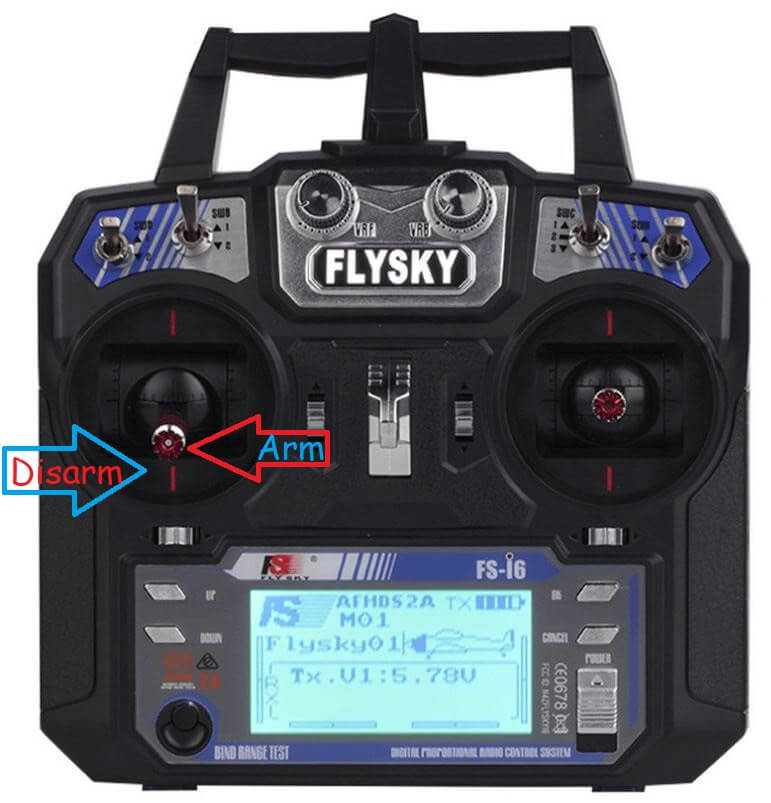
Сначала разместите дрон на ровной и открытой площадке. Затем выполните следующие шаги:
- Подключите аккумулятор дрона. Вы должны услышать упомянутые ранее звуки.
- Включите FlySky. Убедитесь, что батарея заряжена, и устройство чистое от грязи.
- Быстро нажмите стик рыскания влево, чтобы активировать дрон (специфично для этого дрона).
- Моторы дрона должны равномерно увеличивать обороты до 10% дросселя. Дрон не должен взлетать.
- Установите стик дросселя в центральное положение (50% мощности). Дрон должен взлететь и зависнуть на высоте 5 футов.
- Отпустите все управления. Дрон должен зависнуть стабильно и не улетать как пуля.
Заключение
Это был самый масштабный проект, который я когда-либо создавал, и это чудесно. Надеюсь, вам понравилось строить и летать на этом дроне вместе со мной! Увидимся в следующий раз!
Часто задаваемые вопросы
- Сколько времени занимает сборка дрона? — Сборка дрона может занять от нескольких часов до нескольких дней в зависимости от вашего опыта и доступности всех необходимых компонентов.
- Что делать, если дрон не стабилен в полёте? — Проверьте балансировку пропеллеров и моторов, убедитесь, что всё собрано правильно и все компоненты работают.
- Могу ли я использовать другие компоненты, отличные от указанных? — В идеале, используйте именно те компоненты, которые указаны, но если не получается, выбирайте максимально близкие по характеристикам аналоги.
- Как долго дрон может оставаться в воздухе на одной зарядке? — Время полёта дрона на одной зарядке зависит от ёмкости аккумулятора и конфигурации дрона, в среднем это может быть от 10 до 20 минут.
- Что делать, если у меня возникли проблемы с программированием? — Проверьте все подключения, следуйте инструкциям внимательно и, если проблемы не решаются, обратитесь за помощью в комментариях или на форумах.
Гизмо, Индия
Рекомендуем почитать
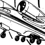 ПСЕВДОРЕАКТИВНЫЕ
Можно смело утверждать, что интерес авиамоделистов к реактивной технике не ослабевал никогда. Однако до последнего времени попытки создания летательных аппаратов с реактивными... МОДЕЛИСТ-КОНСТРУКТОР 2001-02
В НОМЕРЕ: Общественное КБ: В.Петров. Пневмоход-трансформер (2). Малая механизация: Г.Легостаев. Фермерский «Конек» (7). Фирма «Я сам»: А.Коровяновский. Вазу на... токарном станке...